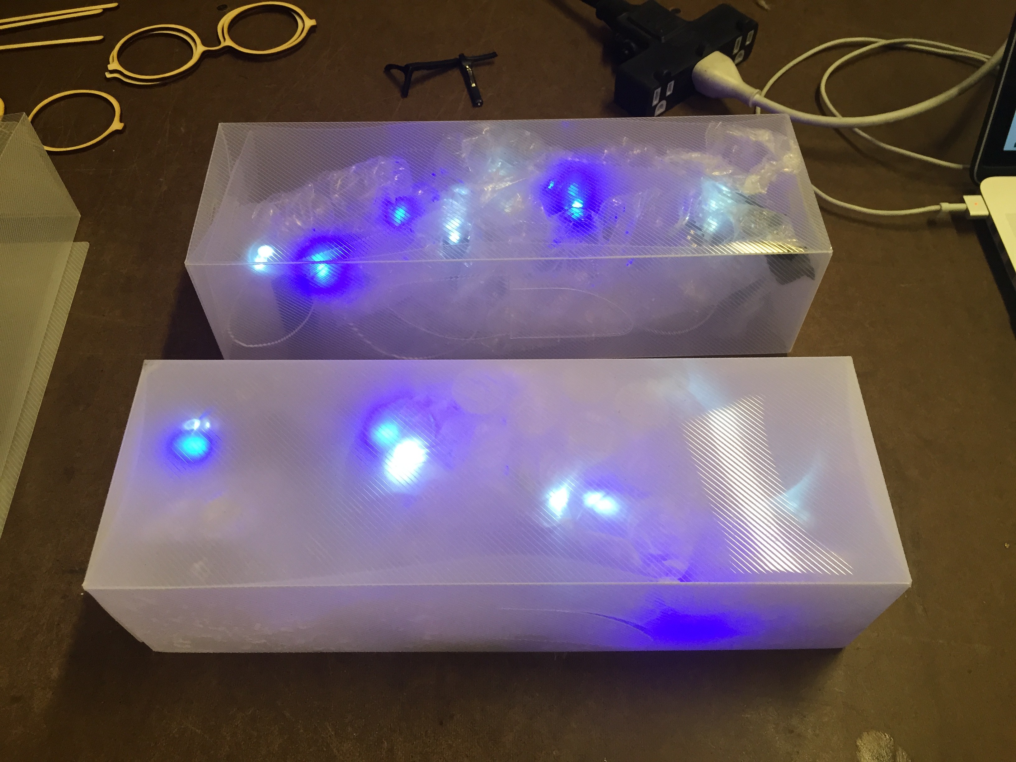
I worked with Serena Parr on this sound project. We decided to create the experience of traveling through space, using sounds inspired by the Voyager recordings. The original idea was to recreate the sounds using our own recordings, but we quickly realized that there was no reason not to use the original recordings.
In the end, I only got two boxes working consistently. And only one of those worked for the in class presentation. It was extremely frustrating. However, I got a lot out of the project and I’m going to continue experimenting with the idea. There are so many objects that are either delicate or intangible, existing on screens or projections. I ended up building a delicate project that couldn’t take the beating I wanted it to, but I’ve got some great next steps:
Experiment with other materials, especially cast foam objects.
Experiment with shapes other than blocks. Although this alters the original idea of building up and knocking over, other shapes could encourage more action. (Like a ball)
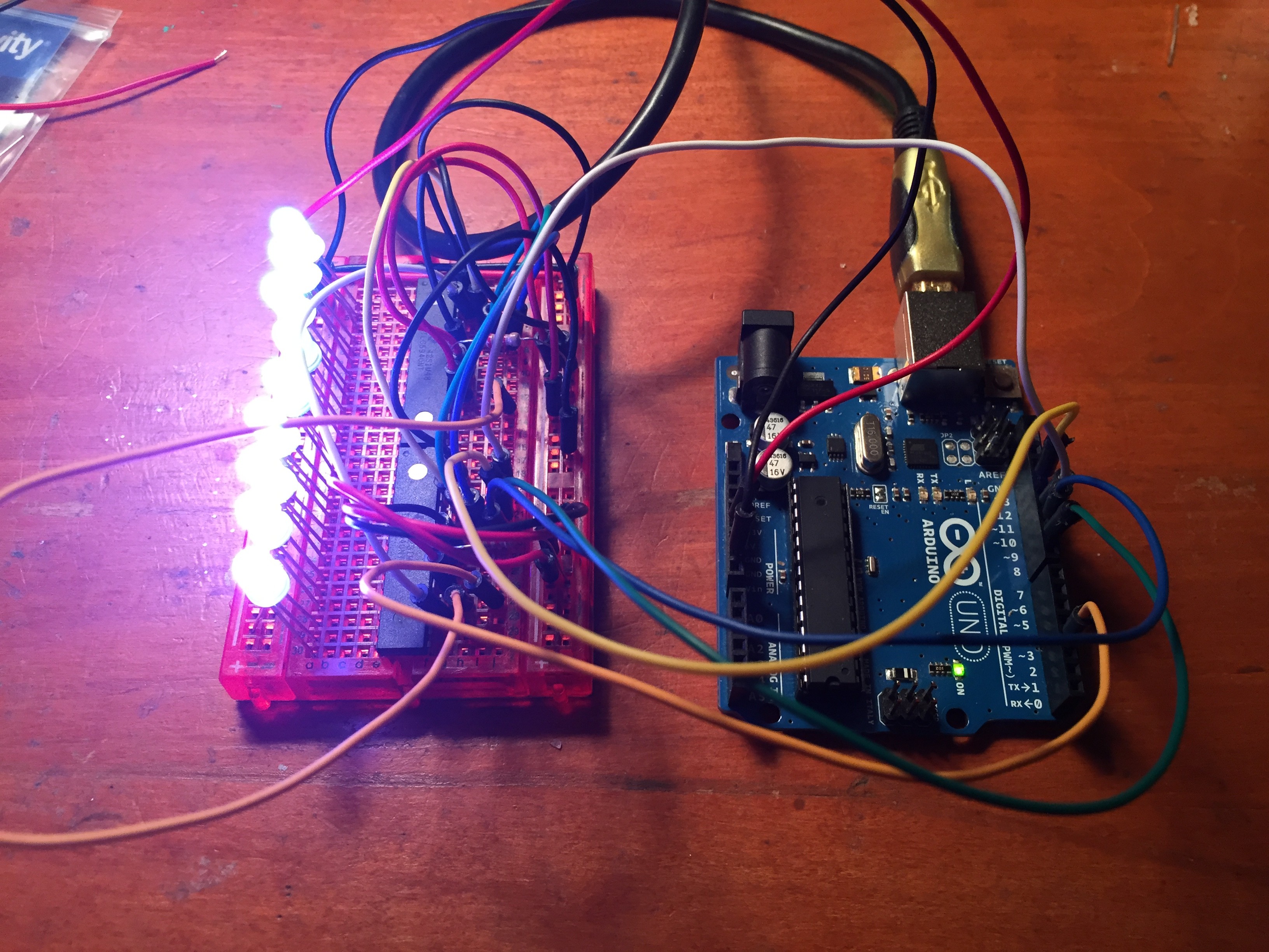
I planned on using the TLC5940NT to drive the LEDs for this project. After finding the TLC5940NT library setting up the LEDs was pretty straightforward. I wrote sketch that would change the LEDs to a color of my choice and it seemed like it was just a matter of dropping that code into the accelerometer sketch.
However, when I combined the TLC5940NT and the ADXL345, things just didn’t work. The LEDs changed to all different colors and they did not respond to the accelerometer. My best guess was that something from the accelerometer was throwing the clock off and that change was affecting the PWM in the TLC5940NTs. Also, I noticed the colors were changing every time the ADXL345 sent an interrupt. There were some good clues to investigate, but it wasn’t something that I really understood or could get fixed before the project presentation. In the end I decided to leave out the TLC5940NT, in favor of a bare bones proof of concept that worked.
Code to change the color of the LEDs, adapted from the TLC5940NT library example code.
/*
    Basic Pin setup:
    ------------                                  ---u----
    ARDUINO   13|-> SCLK (pin 25)           OUT1 |1     28| OUT channel 0
              12|                           OUT2 |2     27|-> GND (VPRG)
              11|-> SIN (pin 26)            OUT3 |3     26|-> SIN (pin 11)
              10|-> BLANK (pin 23)          OUT4 |4     25|-> SCLK (pin 13)
               9|-> XLAT (pin 24)             .  |5     24|-> XLAT (pin 9)
               8|                             .  |6     23|-> BLANK (pin 10)
               7|                             .  |7     22|-> GND
               6|                             .  |8     21|-> VCC (+5V)
               5|                             .  |9     20|-> 2K Resistor -> GND
               4|                             .  |10    19|-> +5V (DCPRG)
               3|-> GSCLK (pin 18)            .  |11    18|-> GSCLK (pin 3)
               2|                             .  |12    17|-> SOUT
               1|                             .  |13    16|-> XERR
               0|                           OUT14|14    15| OUT channel 15
    ------------                                  --------

    -  Put the longer leg (anode) of the LEDs in the +5V and the shorter leg
         (cathode) in OUT(0-15).
    -  +5V from Arduino -> TLC pin 21 and 19     (VCC and DCPRG)
    -  GND from Arduino -> TLC pin 22 and 27     (GND and VPRG)
    -  digital 3        -> TLC pin 18            (GSCLK)
    -  digital 9        -> TLC pin 24            (XLAT)
    -  digital 10       -> TLC pin 23            (BLANK)
    -  digital 11       -> TLC pin 26            (SIN)
    -  digital 13       -> TLC pin 25            (SCLK)
    -  The 2K resistor between TLC pin 20 and GND will let ~20mA through each
       LED.  To be precise, it's I = 39.06 / R (in ohms).  This doesn't depend
       on the LED driving voltage.
    - (Optional): put a pull-up resistor (~10k) between +5V and BLANK so that
                  all the LEDs will turn off when the Arduino is reset.

    If you are daisy-chaining more than one TLC, connect the SOUT of the first
    TLC to the SIN of the next.  All the other pins should just be connected
    together:
        BLANK on Arduino -> BLANK of TLC1 -> BLANK of TLC2 -> ...
        XLAT on Arduino  -> XLAT of TLC1  -> XLAT of TLC2  -> ...
    The one exception is that each TLC needs it's own resistor between pin 20
    and GND.

    This library uses the PWM output ability of digital pins 3, 9, 10, and 11.
    Do not use analogWrite(...) on these pins.

    This sketch does the Knight Rider strobe across a line of LEDs.

    Alex Leone , 2009-02-03 */

#include "Tlc5940.h"

void setup()
{
  /* Call Tlc.init() to setup the tlc.
     You can optionally pass an initial PWM value (0 - 4095) for all channels.*/
  Tlc.init(0);
}

/* This loop will create a Knight Rider-like effect if you have LEDs plugged
   into all the TLC outputs.  NUM_TLCS is defined in "tlc_config.h" in the
   library folder.  After editing tlc_config.h for your setup, delete the
   Tlc5940.o file to save the changes. */

void loop()
{

 showRGB(10000);

  }


void showRGB(int color)
{
  int redIntensity;
  int greenIntensity;
  int blueIntensity;

// This function translates a number between 0 and 767 into a
// specific color on the RGB LED. If you have this number count
// through the whole range (0 to 767), the LED will smoothly
// change color through the entire spectrum.

  // Here we'll use an "if / else" statement to determine which
  // of the three (R,G,B) zones x falls into. Each of these zones
  // spans 4095 because the Tlc5940 wants a number from 0 to 4095.

  // In each of these zones, we'll calculate the brightness
  // for each of the red, green, and blue LEDs within the RGB LED.
  // x = 4096
  // color = a number from 0 to 12287


  if (color <= 4095)          // zone 1
  {
    redIntensity = 4095 - color;    // red goes from on to off
    greenIntensity = color;        // green goes from off to on
    blueIntensity = 0;             // blue is always off
  }
  else if (color <= 8191) // zone 2 { redIntensity = 0; // red is always off greenIntensity = 8191 - (color - 4096); // green on to off blueIntensity = (color - 4096); // blue off to on } else // color >= 8192       // zone 3
  {
    redIntensity = (color - 8192);         // red off to on
    greenIntensity = 0;                   // green is always off
    blueIntensity = 8191 - (color - 8192);  // blue on to off
  }

  // Now that the brightness values have been set, command the LED
  // to those values
  // 1
  Tlc.set(0, redIntensity);
  Tlc.set(1, blueIntensity);
  Tlc.set(2, greenIntensity);
  //2
  Tlc.set(3, redIntensity);
  Tlc.set(4, blueIntensity);
  Tlc.set(5, greenIntensity);
  //3
  Tlc.set(6, redIntensity);
  Tlc.set(7, blueIntensity);
  Tlc.set(8, greenIntensity);
  //4
  Tlc.set(9, redIntensity);
  Tlc.set(10, blueIntensity);
  Tlc.set(11, greenIntensity);
  //5
  Tlc.set(12, redIntensity);
  Tlc.set(13, blueIntensity);
  Tlc.set(14, greenIntensity);
  //6
  Tlc.set(15, redIntensity);
  Tlc.set(16, blueIntensity);
  Tlc.set(17, greenIntensity);
  //7
  Tlc.set(18, redIntensity);
  Tlc.set(19, blueIntensity);
  Tlc.set(20, greenIntensity);
  //8
  Tlc.set(21, redIntensity);
  Tlc.set(22, blueIntensity);
  Tlc.set(23, greenIntensity);
  //9
  Tlc.set(24, redIntensity);
  Tlc.set(25, blueIntensity);
  Tlc.set(26, greenIntensity);
  //10
  Tlc.set(27, redIntensity);
  Tlc.set(28, blueIntensity);
  Tlc.set(29, greenIntensity);
  Tlc.update();
}
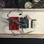
I the original plan was to make a whole bunch of boxes. I didn’t want to use an Arduino in every box, so I was going to use an ATmega328P. I couldn’t even get the Arduino bootloader onto the chip, so that did not work out at all. Also, none of the perfboard circuits I built worked either. I couldn’t find the weak or broken connection on the board, so I ended up just using the breadboard.
I also tried building Arduino shields. They didn’t work either. Making multiples of this project failed big time. It was very annoying.
I had a great deal of trouble with the accelerometers of this project. I tried the ADXL335 and the MPU-6050 (as the MPU-6050 page says, “Reading raw values is easy, the rest is not”). Both accelerometers were good at spitting out data, but it was extremely difficult to get that data to be anything other than seemingly random numbers.
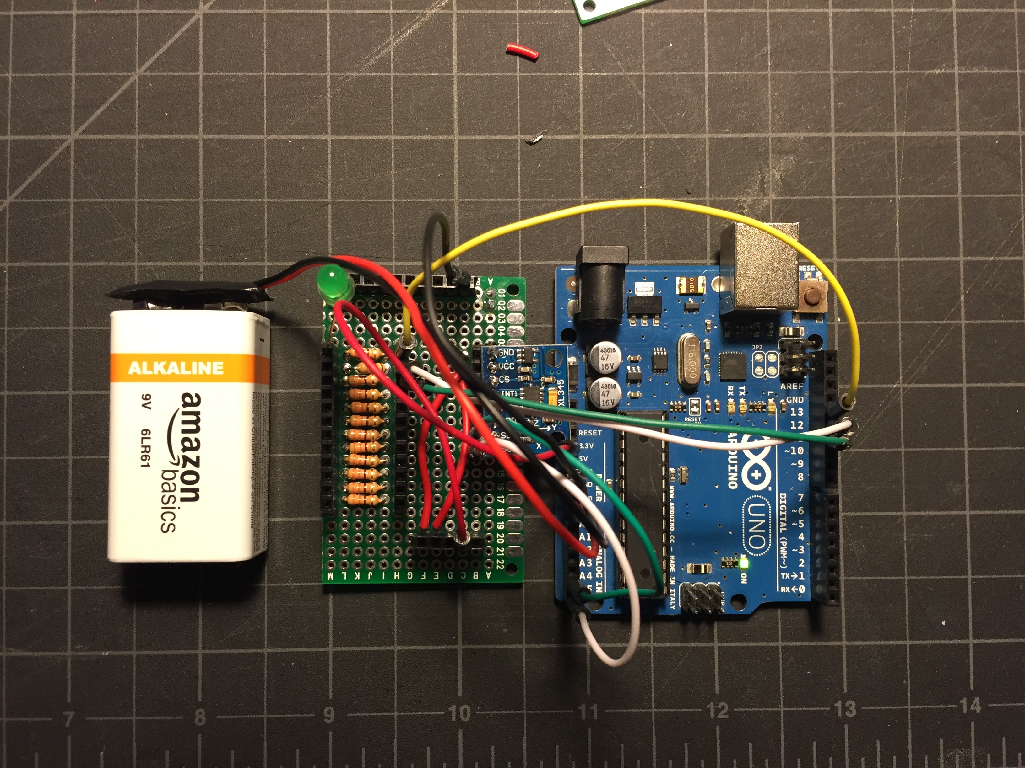
Eventually I found the ADXL345, which is simply the updated version of the ADXL335, and that turned out to be exactly the part that I needed. I combined this tutorial with my RGB LED code from my RGB Pencil project to make an LED light up a specific color when the accelerometer senses a tap, double tap, free fall, and inaction.
Accelerometer Test Top
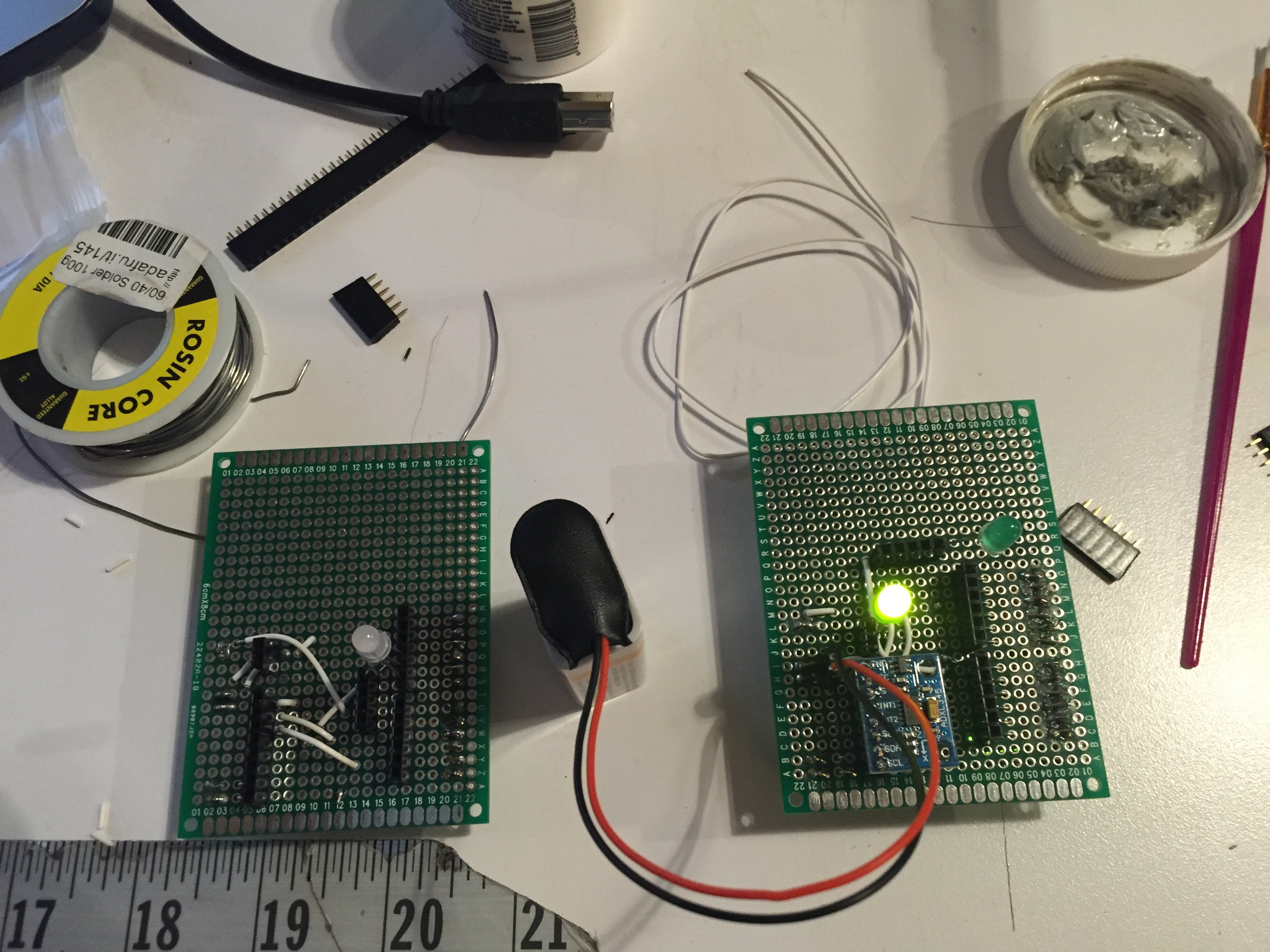
Accelerometer Test Bottom
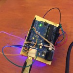
I tested this out by strapping a breadboard to my Arduino and dropping it a whole bunch of times, and it worked just fine. I originally planned on using the TLC5940NT to drive a whole bunch of RGB LEDs, but that did not work out. I ended up simply using the remaining pins on the Arduino.
/Arduino 1.0+ Only!
//Arduino 1.0+ Only!

#include
#include

//Accelerometer code from here: http://bildr.org/2011/03/adxl345-arduino/
ADXL345 adxl; //variable adxl is an instance of the ADXL345 library

int RED_PIN = 13; //set pins for LEDs
int GREEN_PIN = 12;
int BLUE_PIN = 11;
int RED_PIN2 = 10; //set pins for LEDs
int GREEN_PIN2 = 9;
int BLUE_PIN2 = 8;
int RED_PIN3 = 7; //set pins for LEDs
int GREEN_PIN3 = 6;
int BLUE_PIN3 = 5;
int RED_PIN4 = 4; //set pins for LEDs
int GREEN_PIN4 = 3;
int BLUE_PIN4 = 2;


void setup(){
  Serial.begin(9600);
  adxl.powerOn();
  pinMode(RED_PIN, OUTPUT);
  pinMode(GREEN_PIN, OUTPUT);
  pinMode(BLUE_PIN, OUTPUT);
  pinMode(RED_PIN2, OUTPUT);
  pinMode(GREEN_PIN2, OUTPUT);
  pinMode(BLUE_PIN2, OUTPUT);
  pinMode(RED_PIN3, OUTPUT);
  pinMode(GREEN_PIN3, OUTPUT);
  pinMode(BLUE_PIN3, OUTPUT);
  pinMode(RED_PIN4, OUTPUT);
  pinMode(GREEN_PIN4, OUTPUT);
  pinMode(BLUE_PIN4, OUTPUT);

  //set activity/ inactivity thresholds (0-255)
  adxl.setActivityThreshold(75); //62.5mg per increment
  adxl.setInactivityThreshold(75); //62.5mg per increment
  adxl.setTimeInactivity(5); // how many seconds of no activity is inactive?

  //look of activity movement on this axes - 1 == on; 0 == off
  adxl.setActivityX(1);
  adxl.setActivityY(1);
  adxl.setActivityZ(1);

  //look of inactivity movement on this axes - 1 == on; 0 == off
  adxl.setInactivityX(1);
  adxl.setInactivityY(1);
  adxl.setInactivityZ(1);

  //look of tap movement on this axes - 1 == on; 0 == off
  adxl.setTapDetectionOnX(0);
  adxl.setTapDetectionOnY(0);
  adxl.setTapDetectionOnZ(1);

  //set values for what is a tap, and what is a double tap (0-255)
  adxl.setTapThreshold(50); //62.5mg per increment
  adxl.setTapDuration(15); //625μs per increment
  adxl.setDoubleTapLatency(80); //1.25ms per increment
  adxl.setDoubleTapWindow(200); //1.25ms per increment

  //set values for what is considered freefall (0-255)
  adxl.setFreeFallThreshold(5); //(5 - 9) recommended - 62.5mg per increment
  adxl.setFreeFallDuration(20); //(20 - 70) recommended - 5ms per increment

  //setting all interupts to take place on int pin 1
  //I had issues with int pin 2, was unable to reset it
  adxl.setInterruptMapping( ADXL345_INT_SINGLE_TAP_BIT,   ADXL345_INT1_PIN );
  adxl.setInterruptMapping( ADXL345_INT_DOUBLE_TAP_BIT,   ADXL345_INT1_PIN );
  adxl.setInterruptMapping( ADXL345_INT_FREE_FALL_BIT,    ADXL345_INT1_PIN );
  adxl.setInterruptMapping( ADXL345_INT_ACTIVITY_BIT,     ADXL345_INT1_PIN );
  adxl.setInterruptMapping( ADXL345_INT_INACTIVITY_BIT,   ADXL345_INT1_PIN );

  //register interupt actions - 1 == on; 0 == off
  adxl.setInterrupt( ADXL345_INT_SINGLE_TAP_BIT, 1);
  adxl.setInterrupt( ADXL345_INT_DOUBLE_TAP_BIT, 1);
  adxl.setInterrupt( ADXL345_INT_FREE_FALL_BIT,  1);
  adxl.setInterrupt( ADXL345_INT_ACTIVITY_BIT,   1);
  adxl.setInterrupt( ADXL345_INT_INACTIVITY_BIT, 1);
}

void loop(){

  //Boring accelerometer stuff
  int x,y,z;
  adxl.readAccel(&x, &y, &z); //read the accelerometer values and store them in variables  x,y,z

  // Output x,y,z values - Commented out
  //Serial.print(x);
  //Serial.print(y);
  //Serial.println(z);


  //Fun Stuff!
  //read interrupts source and look for triggerd actions

  //getInterruptSource clears all triggered actions after returning value
  //so do not call again until you need to recheck for triggered actions
   byte interrupts = adxl.getInterruptSource();

  // freefall
  if(adxl.triggered(interrupts, ADXL345_FREE_FALL)){
    Serial.println("freefall");
    showRGB(200);
  }

  //inactivity
  if(adxl.triggered(interrupts, ADXL345_INACTIVITY)){
    Serial.println("inactivity");
     showRGB(400);
  }

  //activity
  if(adxl.triggered(interrupts, ADXL345_ACTIVITY)){
    Serial.println("activity");
     showRGB(700);
  }

  //double tap
  if(adxl.triggered(interrupts, ADXL345_DOUBLE_TAP)){
    Serial.println("double tap");
     showRGB(300);
  }

  //tap
  if(adxl.triggered(interrupts, ADXL345_SINGLE_TAP)){
    Serial.println("tap");
    showRGB(100);
  }


}


void showRGB(int color)
{
  int redIntensity;
  int greenIntensity;
  int blueIntensity;

  // Here we'll use an "if / else" statement to determine which
  // of the three (R,G,B) zones x falls into. Each of these zones
  // spans 255 because analogWrite() wants a number from 0 to 255.

  // In each of these zones, we'll calculate the brightness
  // for each of the red, green, and blue LEDs within the RGB LED.

  if (color <= 255)          // zone 1
  {
    redIntensity = 255 - color;    // red goes from on to off
    greenIntensity = color;        // green goes from off to on
    blueIntensity = 0;             // blue is always off
  }
  else if (color <= 511) // zone 2 { redIntensity = 0; // red is always off greenIntensity = 255 - (color - 256); // green on to off blueIntensity = (color - 256); // blue off to on } else // color >= 512       // zone 3
  {
    redIntensity = (color - 512);         // red off to on
    greenIntensity = 0;                   // green is always off
    blueIntensity = 255 - (color - 512);  // blue on to off
  }

  // Now that the brightness values have been set, command the LED
  // to those values

  analogWrite(RED_PIN, redIntensity);
  analogWrite(BLUE_PIN, blueIntensity);
  analogWrite(GREEN_PIN, greenIntensity);
  analogWrite(RED_PIN2, redIntensity);
  analogWrite(BLUE_PIN2, blueIntensity);
  analogWrite(GREEN_PIN2, greenIntensity);
  analogWrite(RED_PIN3, redIntensity);
  analogWrite(BLUE_PIN3, blueIntensity);
  analogWrite(GREEN_PIN3, greenIntensity);
  analogWrite(RED_PIN4, redIntensity);
  analogWrite(BLUE_PIN4, blueIntensity);
  analogWrite(GREEN_PIN4, greenIntensity);
}
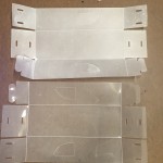
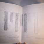
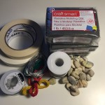
One of the main pieces of feedback that I got from play-testing was that the boxes seemed to delicate to really throw or kick, partially because they could see the electronics inside. So, I decided to frost the interior of the boxes. The material tests went well and the frost held up to the kicking and dropping, but not to opening and closing the boxes. The paint has no elasticity and started just flaking off.
Other material options include making the boxes from plank foam, frosting the boxes with contact paper instead of spray, or casting custom shapes from foam. I’m interested in experimenting with casting shapes, but I’d also like to try and maintain the ‘building block’ component of this idea. I’m guessing that this is going to end in a bunch of experiments and idea doodles.
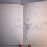
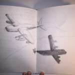
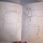
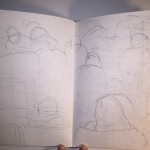
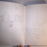
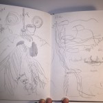
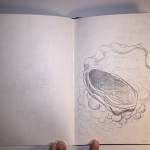
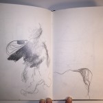
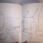
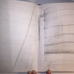
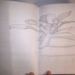
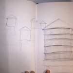
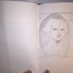
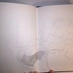
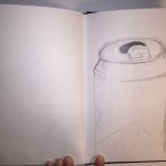
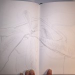
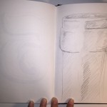
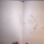
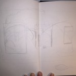
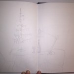
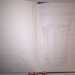
I found myself falling back a lot on my fine arts training for the sketchbook project. Without thinking about it I chose to draw almost exclusively from life, something that was always stressed in my drawing classes, and in graphite, my medium of choice for undergrad. I’ve excluded all the project sketches and notes from this collection, as I wasn’t making them with this exercise in mind.
I didn’t enter this assignment with any real plan, except to draw what struck my fancy on any given day. Looking at all the drawings together it’s easy to see them as a record of where I spent my time. There are several drawings of the kitchen table, wine bottles and glasses, and home interiors. It’s probably not surprising that there’s a view of water towers from my office or a lot of plants in my apartment.
I enjoyed this assignment, but I did have trouble remembering to do the drawings every day. I would often find myself doing them in twos and threes as I was making up for missed days.
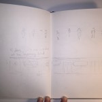
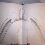
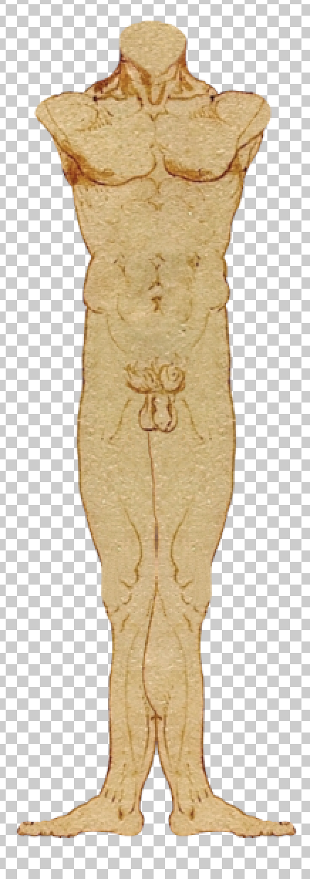
Viniyata and I partnered up again for the second animation assignment. We ran through a number of ideas for this project, from a riff on the little mermaid to a hypnotic pocket watch pendulum. Eventually we settled on something using DaVinci’s Vitruvian Man. The drawing seemed like a good way to explore animating the human form, without having to invent a character. It also allowed us to explore shapes and patterns, which seemed pretty cool.
We storyboarded out the idea, then divided the work into two parts: prepping and animating the Vitruvian Man himself and then duplicating and animating the original animation. I took animating the Vitruvian Man, who I eventually grew really really tired of.
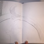
Cutting up the Vitruvian Man into parts was straightforward, but tedious. I thought of him like a paper doll. I spent quite a bit of time duplicating layers to separate each arm, fore arm, and upper arm into three distinct pieces. It was the same process for each thigh, calf, and foot. After cutting everything up in Photoshop, I took everything into After Effects to test it out. The figure needed a lot of adjustments, and that also took a fair amount of time.
Something that we hadn’t considered when we first picked the Vitruvian Man is that only one of his legs can really bend, due to how they are positioned in space. I solved this by mirroring the leg that can bend. This looks a little silly, but you can’t really tell in the animation.
I created the figure’s animation by with rotations and parent/child pairings. I was trying to keep the motions angular and ‘mathematical’, but also make them seem human. I think that works. After finishing the figure animation I handed the composition off to Viniyata.
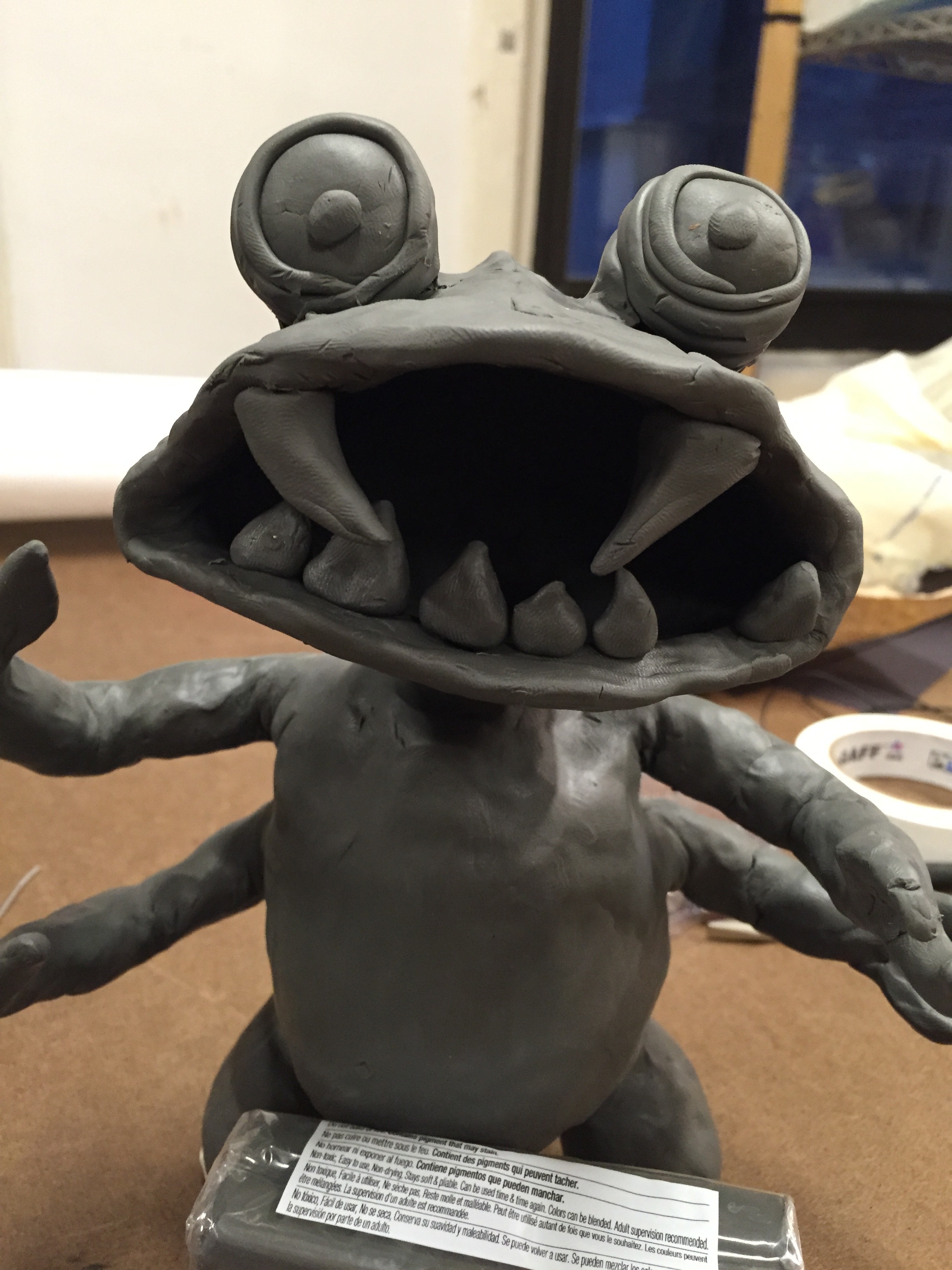
When Viniyata and I met to shoot our animation, it became clear that our original idea was not feasible to shoot on the floor. So, we quickly reconsidered what the strengths of our idea were and considered what we could do with them. We realized that we had not one, but two charismatic little monsters. We also had the fact that we were learning stop motion animation.
We decided to combine those two facts and create an animation about the animation process. The sequence would include us setting up the stage, adjusting the camera, and beginning to animate the first monster. Then, the second, larger monster would eat the first, as new ideas consuming the old. Finally, the larger monster would lunge at the camera, turning on its creators.
This was a lot of fun to shoot, even though we had a couple of problems. The little monster was not designed to bear any weight, to having him old things mean that his arms would slowly move as we were shooting. Also, the large monster wasn’t designed to walk, so making that animation was tricky. However, in the end I think the animation was pretty successful.
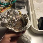
Weighting the monster’s butt with sand, to act as a counter weight to his head.
I covered the armature with gaffers tape and then spread clay over the tape
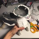
Monster!
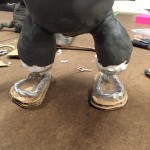
We realized that the monster needed feet, so I added them after the fact.
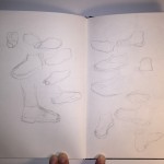
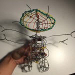
I built a bigger better monster based on our clay sketch. I built him from 16 and 22 gauge armature wire, gaffers tape, clay, and other miscellaneous items I found in my apartment. The idea was to put a gaffers tape skin over the armature, and then cover it in clay. That way the monster would be lighter and have a good range of motion. Also, the monster’s feed and torso were weighted with sand and rocks to give more stability.
After blocking out the animation it became clear that the monster needed feet, so I added them after the fact. During the animation process I realized that I should have also given the monster knees.