In the end, I only got two boxes working consistently. And only one of those worked for the in class presentation. It was extremely frustrating. However, I got a lot out of the project and I’m going to continue experimenting with the idea. There are so many objects that are either delicate or intangible, existing on screens or projections. I ended up building a delicate project that couldn’t take the beating I wanted it to, but I’ve got some great next steps:
Experiment with other materials, especially cast foam objects.
Experiment with shapes other than blocks. Although this alters the original idea of building up and knocking over, other shapes could encourage more action. (Like a ball)
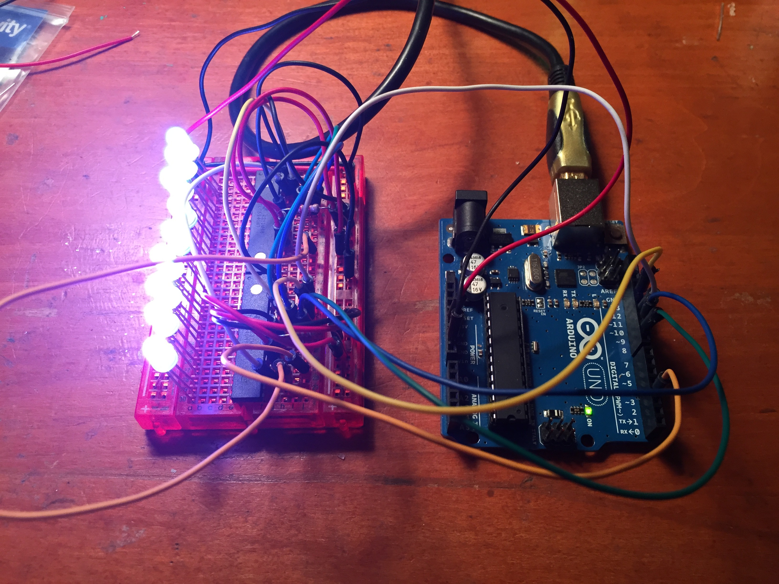
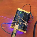
I planned on using the TLC5940NT to drive the LEDs for this project. After finding the TLC5940NT library setting up the LEDs was pretty straightforward. I wrote sketch that would change the LEDs to a color of my choice and it seemed like it was just a matter of dropping that code into the accelerometer sketch.
However, when I combined the TLC5940NT and the ADXL345, things just didn’t work. The LEDs changed to all different colors and they did not respond to the accelerometer. My best guess was that something from the accelerometer was throwing the clock off and that change was affecting the PWM in the TLC5940NTs. Also, I noticed the colors were changing every time the ADXL345 sent an interrupt. There were some good clues to investigate, but it wasn’t something that I really understood or could get fixed before the project presentation. In the end I decided to leave out the TLC5940NT, in favor of a bare bones proof of concept that worked.
Code to change the color of the LEDs, adapted from the TLC5940NT library example code.
/*
    Basic Pin setup:
    ------------                                  ---u----
    ARDUINO   13|-> SCLK (pin 25)           OUT1 |1     28| OUT channel 0
              12|                           OUT2 |2     27|-> GND (VPRG)
              11|-> SIN (pin 26)            OUT3 |3     26|-> SIN (pin 11)
              10|-> BLANK (pin 23)          OUT4 |4     25|-> SCLK (pin 13)
               9|-> XLAT (pin 24)             .  |5     24|-> XLAT (pin 9)
               8|                             .  |6     23|-> BLANK (pin 10)
               7|                             .  |7     22|-> GND
               6|                             .  |8     21|-> VCC (+5V)
               5|                             .  |9     20|-> 2K Resistor -> GND
               4|                             .  |10    19|-> +5V (DCPRG)
               3|-> GSCLK (pin 18)            .  |11    18|-> GSCLK (pin 3)
               2|                             .  |12    17|-> SOUT
               1|                             .  |13    16|-> XERR
               0|                           OUT14|14    15| OUT channel 15
    ------------                                  --------

    -  Put the longer leg (anode) of the LEDs in the +5V and the shorter leg
         (cathode) in OUT(0-15).
    -  +5V from Arduino -> TLC pin 21 and 19     (VCC and DCPRG)
    -  GND from Arduino -> TLC pin 22 and 27     (GND and VPRG)
    -  digital 3        -> TLC pin 18            (GSCLK)
    -  digital 9        -> TLC pin 24            (XLAT)
    -  digital 10       -> TLC pin 23            (BLANK)
    -  digital 11       -> TLC pin 26            (SIN)
    -  digital 13       -> TLC pin 25            (SCLK)
    -  The 2K resistor between TLC pin 20 and GND will let ~20mA through each
       LED.  To be precise, it's I = 39.06 / R (in ohms).  This doesn't depend
       on the LED driving voltage.
    - (Optional): put a pull-up resistor (~10k) between +5V and BLANK so that
                  all the LEDs will turn off when the Arduino is reset.

    If you are daisy-chaining more than one TLC, connect the SOUT of the first
    TLC to the SIN of the next.  All the other pins should just be connected
    together:
        BLANK on Arduino -> BLANK of TLC1 -> BLANK of TLC2 -> ...
        XLAT on Arduino  -> XLAT of TLC1  -> XLAT of TLC2  -> ...
    The one exception is that each TLC needs it's own resistor between pin 20
    and GND.

    This library uses the PWM output ability of digital pins 3, 9, 10, and 11.
    Do not use analogWrite(...) on these pins.

    This sketch does the Knight Rider strobe across a line of LEDs.

    Alex Leone , 2009-02-03 */

#include "Tlc5940.h"

void setup()
{
  /* Call Tlc.init() to setup the tlc.
     You can optionally pass an initial PWM value (0 - 4095) for all channels.*/
  Tlc.init(0);
}

/* This loop will create a Knight Rider-like effect if you have LEDs plugged
   into all the TLC outputs.  NUM_TLCS is defined in "tlc_config.h" in the
   library folder.  After editing tlc_config.h for your setup, delete the
   Tlc5940.o file to save the changes. */

void loop()
{

 showRGB(10000);

  }


void showRGB(int color)
{
  int redIntensity;
  int greenIntensity;
  int blueIntensity;

// This function translates a number between 0 and 767 into a
// specific color on the RGB LED. If you have this number count
// through the whole range (0 to 767), the LED will smoothly
// change color through the entire spectrum.

  // Here we'll use an "if / else" statement to determine which
  // of the three (R,G,B) zones x falls into. Each of these zones
  // spans 4095 because the Tlc5940 wants a number from 0 to 4095.

  // In each of these zones, we'll calculate the brightness
  // for each of the red, green, and blue LEDs within the RGB LED.
  // x = 4096
  // color = a number from 0 to 12287


  if (color <= 4095)          // zone 1
  {
    redIntensity = 4095 - color;    // red goes from on to off
    greenIntensity = color;        // green goes from off to on
    blueIntensity = 0;             // blue is always off
  }
  else if (color <= 8191) // zone 2 { redIntensity = 0; // red is always off greenIntensity = 8191 - (color - 4096); // green on to off blueIntensity = (color - 4096); // blue off to on } else // color >= 8192       // zone 3
  {
    redIntensity = (color - 8192);         // red off to on
    greenIntensity = 0;                   // green is always off
    blueIntensity = 8191 - (color - 8192);  // blue on to off
  }

  // Now that the brightness values have been set, command the LED
  // to those values
  // 1
  Tlc.set(0, redIntensity);
  Tlc.set(1, blueIntensity);
  Tlc.set(2, greenIntensity);
  //2
  Tlc.set(3, redIntensity);
  Tlc.set(4, blueIntensity);
  Tlc.set(5, greenIntensity);
  //3
  Tlc.set(6, redIntensity);
  Tlc.set(7, blueIntensity);
  Tlc.set(8, greenIntensity);
  //4
  Tlc.set(9, redIntensity);
  Tlc.set(10, blueIntensity);
  Tlc.set(11, greenIntensity);
  //5
  Tlc.set(12, redIntensity);
  Tlc.set(13, blueIntensity);
  Tlc.set(14, greenIntensity);
  //6
  Tlc.set(15, redIntensity);
  Tlc.set(16, blueIntensity);
  Tlc.set(17, greenIntensity);
  //7
  Tlc.set(18, redIntensity);
  Tlc.set(19, blueIntensity);
  Tlc.set(20, greenIntensity);
  //8
  Tlc.set(21, redIntensity);
  Tlc.set(22, blueIntensity);
  Tlc.set(23, greenIntensity);
  //9
  Tlc.set(24, redIntensity);
  Tlc.set(25, blueIntensity);
  Tlc.set(26, greenIntensity);
  //10
  Tlc.set(27, redIntensity);
  Tlc.set(28, blueIntensity);
  Tlc.set(29, greenIntensity);
  Tlc.update();
}
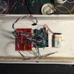
I the original plan was to make a whole bunch of boxes. I didn’t want to use an Arduino in every box, so I was going to use an ATmega328P. I couldn’t even get the Arduino bootloader onto the chip, so that did not work out at all. Also, none of the perfboard circuits I built worked either. I couldn’t find the weak or broken connection on the board, so I ended up just using the breadboard.
I also tried building Arduino shields. They didn’t work either. Making multiples of this project failed big time. It was very annoying.
I had a great deal of trouble with the accelerometers of this project. I tried the ADXL335 and the MPU-6050 (as the MPU-6050 page says, “Reading raw values is easy, the rest is not”). Both accelerometers were good at spitting out data, but it was extremely difficult to get that data to be anything other than seemingly random numbers.
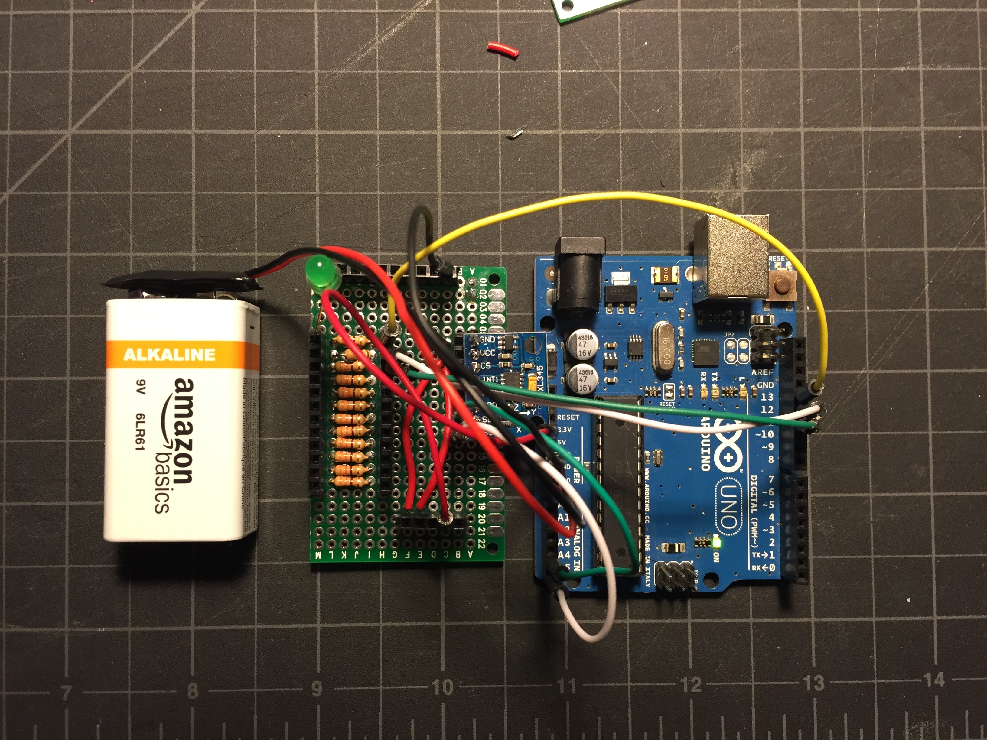
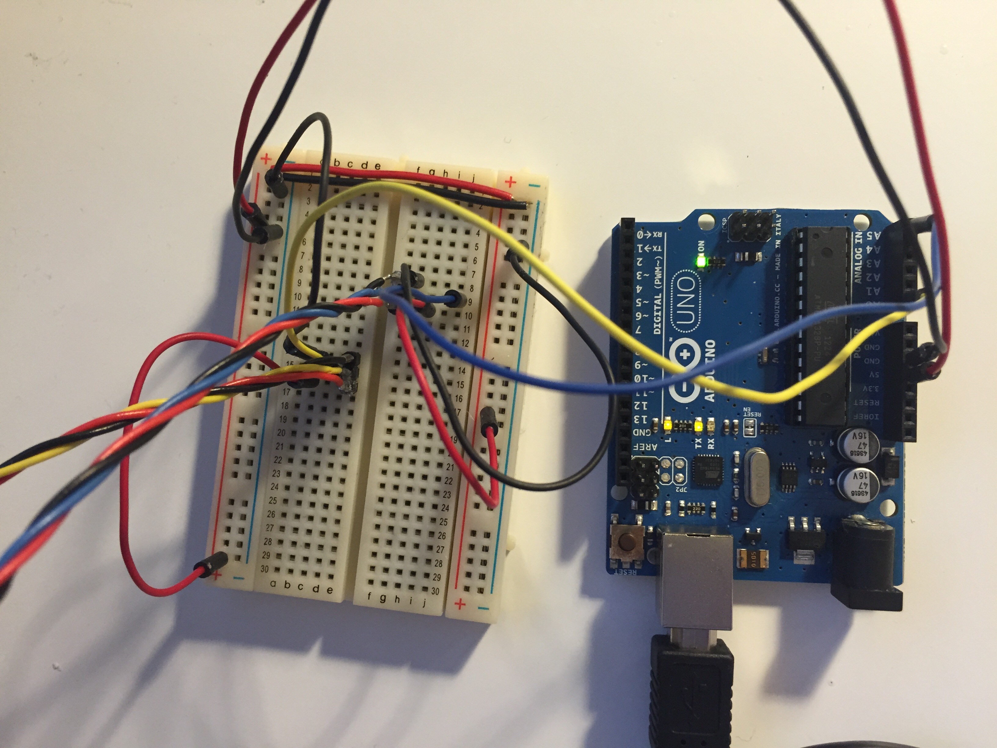
Eventually I found the ADXL345, which is simply the updated version of the ADXL335, and that turned out to be exactly the part that I needed. I combined this tutorial with my RGB LED code from my RGB Pencil project to make an LED light up a specific color when the accelerometer senses a tap, double tap, free fall, and inaction.
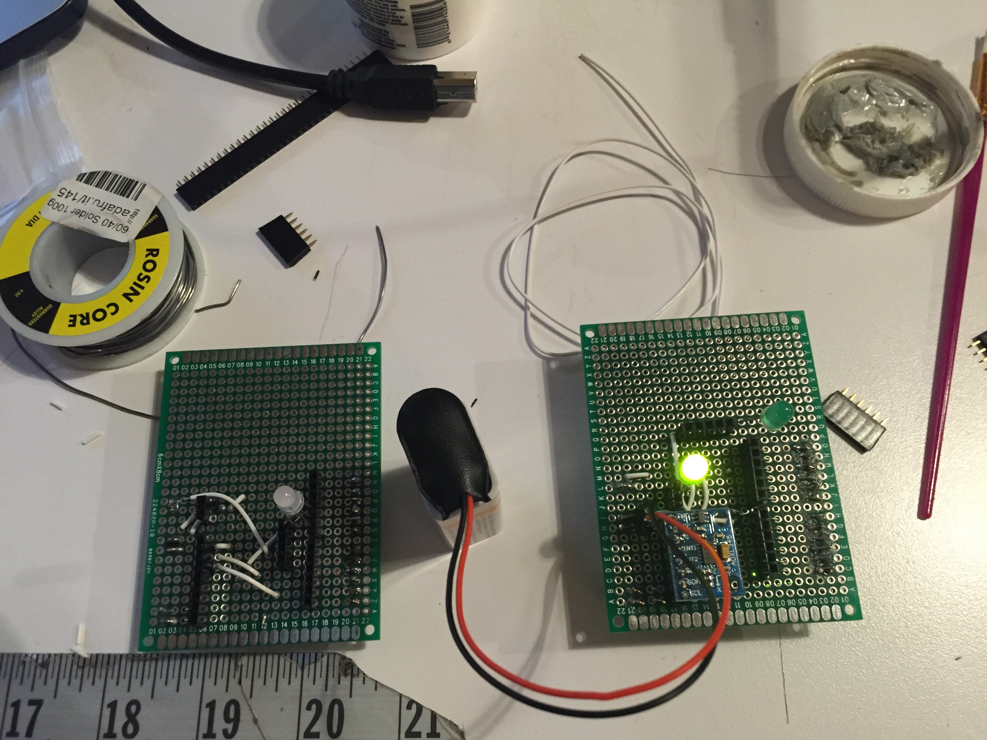
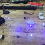
Accelerometer Test Top
Accelerometer Test Bottom
I tested this out by strapping a breadboard to my Arduino and dropping it a whole bunch of times, and it worked just fine. I originally planned on using the TLC5940NT to drive a whole bunch of RGB LEDs, but that did not work out. I ended up simply using the remaining pins on the Arduino.
/Arduino 1.0+ Only!
//Arduino 1.0+ Only!

#include
#include

//Accelerometer code from here: http://bildr.org/2011/03/adxl345-arduino/
ADXL345 adxl; //variable adxl is an instance of the ADXL345 library

int RED_PIN = 13; //set pins for LEDs
int GREEN_PIN = 12;
int BLUE_PIN = 11;
int RED_PIN2 = 10; //set pins for LEDs
int GREEN_PIN2 = 9;
int BLUE_PIN2 = 8;
int RED_PIN3 = 7; //set pins for LEDs
int GREEN_PIN3 = 6;
int BLUE_PIN3 = 5;
int RED_PIN4 = 4; //set pins for LEDs
int GREEN_PIN4 = 3;
int BLUE_PIN4 = 2;


void setup(){
  Serial.begin(9600);
  adxl.powerOn();
  pinMode(RED_PIN, OUTPUT);
  pinMode(GREEN_PIN, OUTPUT);
  pinMode(BLUE_PIN, OUTPUT);
  pinMode(RED_PIN2, OUTPUT);
  pinMode(GREEN_PIN2, OUTPUT);
  pinMode(BLUE_PIN2, OUTPUT);
  pinMode(RED_PIN3, OUTPUT);
  pinMode(GREEN_PIN3, OUTPUT);
  pinMode(BLUE_PIN3, OUTPUT);
  pinMode(RED_PIN4, OUTPUT);
  pinMode(GREEN_PIN4, OUTPUT);
  pinMode(BLUE_PIN4, OUTPUT);

  //set activity/ inactivity thresholds (0-255)
  adxl.setActivityThreshold(75); //62.5mg per increment
  adxl.setInactivityThreshold(75); //62.5mg per increment
  adxl.setTimeInactivity(5); // how many seconds of no activity is inactive?

  //look of activity movement on this axes - 1 == on; 0 == off
  adxl.setActivityX(1);
  adxl.setActivityY(1);
  adxl.setActivityZ(1);

  //look of inactivity movement on this axes - 1 == on; 0 == off
  adxl.setInactivityX(1);
  adxl.setInactivityY(1);
  adxl.setInactivityZ(1);

  //look of tap movement on this axes - 1 == on; 0 == off
  adxl.setTapDetectionOnX(0);
  adxl.setTapDetectionOnY(0);
  adxl.setTapDetectionOnZ(1);

  //set values for what is a tap, and what is a double tap (0-255)
  adxl.setTapThreshold(50); //62.5mg per increment
  adxl.setTapDuration(15); //625μs per increment
  adxl.setDoubleTapLatency(80); //1.25ms per increment
  adxl.setDoubleTapWindow(200); //1.25ms per increment

  //set values for what is considered freefall (0-255)
  adxl.setFreeFallThreshold(5); //(5 - 9) recommended - 62.5mg per increment
  adxl.setFreeFallDuration(20); //(20 - 70) recommended - 5ms per increment

  //setting all interupts to take place on int pin 1
  //I had issues with int pin 2, was unable to reset it
  adxl.setInterruptMapping( ADXL345_INT_SINGLE_TAP_BIT,   ADXL345_INT1_PIN );
  adxl.setInterruptMapping( ADXL345_INT_DOUBLE_TAP_BIT,   ADXL345_INT1_PIN );
  adxl.setInterruptMapping( ADXL345_INT_FREE_FALL_BIT,    ADXL345_INT1_PIN );
  adxl.setInterruptMapping( ADXL345_INT_ACTIVITY_BIT,     ADXL345_INT1_PIN );
  adxl.setInterruptMapping( ADXL345_INT_INACTIVITY_BIT,   ADXL345_INT1_PIN );

  //register interupt actions - 1 == on; 0 == off
  adxl.setInterrupt( ADXL345_INT_SINGLE_TAP_BIT, 1);
  adxl.setInterrupt( ADXL345_INT_DOUBLE_TAP_BIT, 1);
  adxl.setInterrupt( ADXL345_INT_FREE_FALL_BIT,  1);
  adxl.setInterrupt( ADXL345_INT_ACTIVITY_BIT,   1);
  adxl.setInterrupt( ADXL345_INT_INACTIVITY_BIT, 1);
}

void loop(){

  //Boring accelerometer stuff
  int x,y,z;
  adxl.readAccel(&x, &y, &z); //read the accelerometer values and store them in variables  x,y,z

  // Output x,y,z values - Commented out
  //Serial.print(x);
  //Serial.print(y);
  //Serial.println(z);


  //Fun Stuff!
  //read interrupts source and look for triggerd actions

  //getInterruptSource clears all triggered actions after returning value
  //so do not call again until you need to recheck for triggered actions
   byte interrupts = adxl.getInterruptSource();

  // freefall
  if(adxl.triggered(interrupts, ADXL345_FREE_FALL)){
    Serial.println("freefall");
    showRGB(200);
  }

  //inactivity
  if(adxl.triggered(interrupts, ADXL345_INACTIVITY)){
    Serial.println("inactivity");
     showRGB(400);
  }

  //activity
  if(adxl.triggered(interrupts, ADXL345_ACTIVITY)){
    Serial.println("activity");
     showRGB(700);
  }

  //double tap
  if(adxl.triggered(interrupts, ADXL345_DOUBLE_TAP)){
    Serial.println("double tap");
     showRGB(300);
  }

  //tap
  if(adxl.triggered(interrupts, ADXL345_SINGLE_TAP)){
    Serial.println("tap");
    showRGB(100);
  }


}


void showRGB(int color)
{
  int redIntensity;
  int greenIntensity;
  int blueIntensity;

  // Here we'll use an "if / else" statement to determine which
  // of the three (R,G,B) zones x falls into. Each of these zones
  // spans 255 because analogWrite() wants a number from 0 to 255.

  // In each of these zones, we'll calculate the brightness
  // for each of the red, green, and blue LEDs within the RGB LED.

  if (color <= 255)          // zone 1
  {
    redIntensity = 255 - color;    // red goes from on to off
    greenIntensity = color;        // green goes from off to on
    blueIntensity = 0;             // blue is always off
  }
  else if (color <= 511) // zone 2 { redIntensity = 0; // red is always off greenIntensity = 255 - (color - 256); // green on to off blueIntensity = (color - 256); // blue off to on } else // color >= 512       // zone 3
  {
    redIntensity = (color - 512);         // red off to on
    greenIntensity = 0;                   // green is always off
    blueIntensity = 255 - (color - 512);  // blue on to off
  }

  // Now that the brightness values have been set, command the LED
  // to those values

  analogWrite(RED_PIN, redIntensity);
  analogWrite(BLUE_PIN, blueIntensity);
  analogWrite(GREEN_PIN, greenIntensity);
  analogWrite(RED_PIN2, redIntensity);
  analogWrite(BLUE_PIN2, blueIntensity);
  analogWrite(GREEN_PIN2, greenIntensity);
  analogWrite(RED_PIN3, redIntensity);
  analogWrite(BLUE_PIN3, blueIntensity);
  analogWrite(GREEN_PIN3, greenIntensity);
  analogWrite(RED_PIN4, redIntensity);
  analogWrite(BLUE_PIN4, blueIntensity);
  analogWrite(GREEN_PIN4, greenIntensity);
}
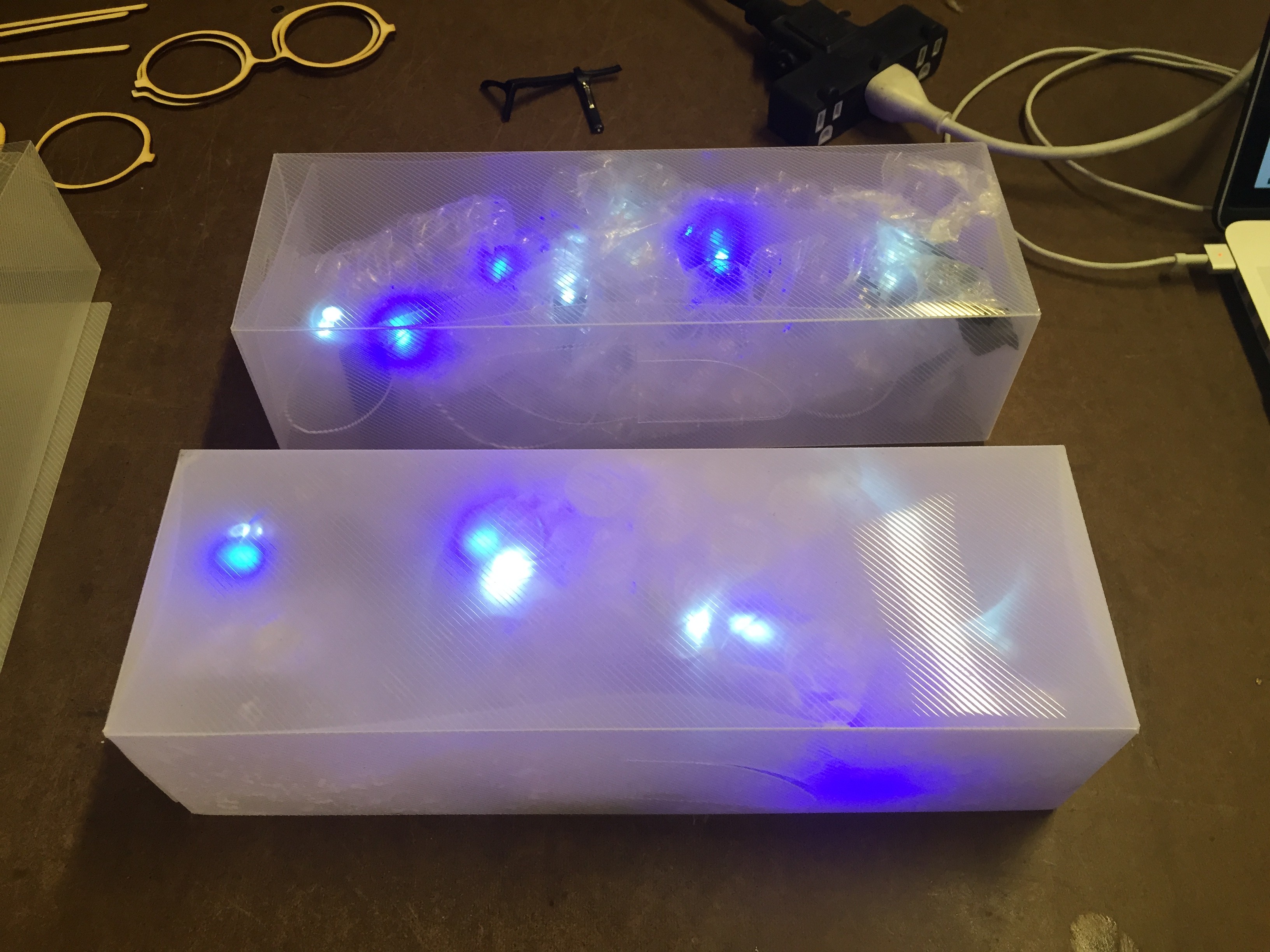
One of the main pieces of feedback that I got from play-testing was that the boxes seemed to delicate to really throw or kick, partially because they could see the electronics inside. So, I decided to frost the interior of the boxes. The material tests went well and the frost held up to the kicking and dropping, but not to opening and closing the boxes. The paint has no elasticity and started just flaking off.
Other material options include making the boxes from plank foam, frosting the boxes with contact paper instead of spray, or casting custom shapes from foam. I’m interested in experimenting with casting shapes, but I’d also like to try and maintain the ‘building block’ component of this idea. I’m guessing that this is going to end in a bunch of experiments and idea doodles.
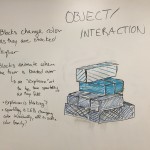
I went into the play testing for this project without doing any substantial planning for the project, or even a clear idea about how to achieve the effects I wanted technically. During the play testing Danny suggested that I could achieve most of what I wanted with an accelerometer, and I think that this is true. The basic interaction for this project is:
The accelerometer knows it is on the floor
1. A person stacks a block on top of another block The accelerometer senses the change in the X-Axis The LEDs change color according to the height, creating color gradient
2. A tower is knocked over The accelerometer senses the change in the X-Axis The LEDs change color according to the height, creating explosion and sparkle effect
3. The blocks are back on the floor The accelerometer senses the change in the X-Axis The LEDs chage color according to the height, resets to the base color
4. Repeat
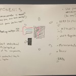
With that in mind the components in each box will be:
I’m sure that I will end up needing other components and materials as I test and prototype everything, but that list should be what’s at the heart of each box.
Something that won’t make it into this version, as it’s not central to the concept, but that I would love to add to a future version is the MRF24J40MA-I/RM (RF Transceiver Module). It would be a great way to let the boxes communicate with each other and other, as of yet unimagined, components.
My current build plan is:
But that is highly dependent on all the different component orders arriving in a timely manner. I think that one of the main challenges of this project, besides simply getting everything working, will be allowing enough time to make multiple blocks.
My original pitch for the P Comp final was “I want to smash things”. I was fed up with projects that were tied to laptops and other delicate technology or projections that have no corporeal presence. Instead, I wanted to make something that existed as an object on its own that required a fully physicality.
I considered a number of different ideas (including conductive smashables and foam bananas) but eventually settled on light up blocks that can be used to build a tower and then knocked down! I’m hoping to capture the childlike joy of building, then destroying.
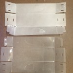
For the play test I wanted to see if people would build a tower and then knock it over if I provided the blocks. I also wanted to use the opportunity as a quick materials test for the plastic boxes I’d sourced.
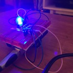
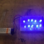
LED Breadboard Test
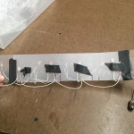
LEDs Soldiered Up
LEDs Taped to Plastic Mount
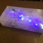
Block Interior with LEDs and Bubble Wrap
Block Closed
Block Illuminated
I wired up some LEDs to see how they would look inside the plastic boxes and to see how they would hold up to being thrown around.
My take-aways from the play testing were:
No one knocked the tower over on their own.
People generally wanted more interaction, wanted the blocks to do more or to have more of a construct around the interaction.
More people played with the blocks on the floor than expected.
If they change to the same color each time it gets boring.
Maybe they shouldn’t change color at all until they fall.
ITP people/ adults might treat things too delicately. (But people really liked it after they knew they could kick it)
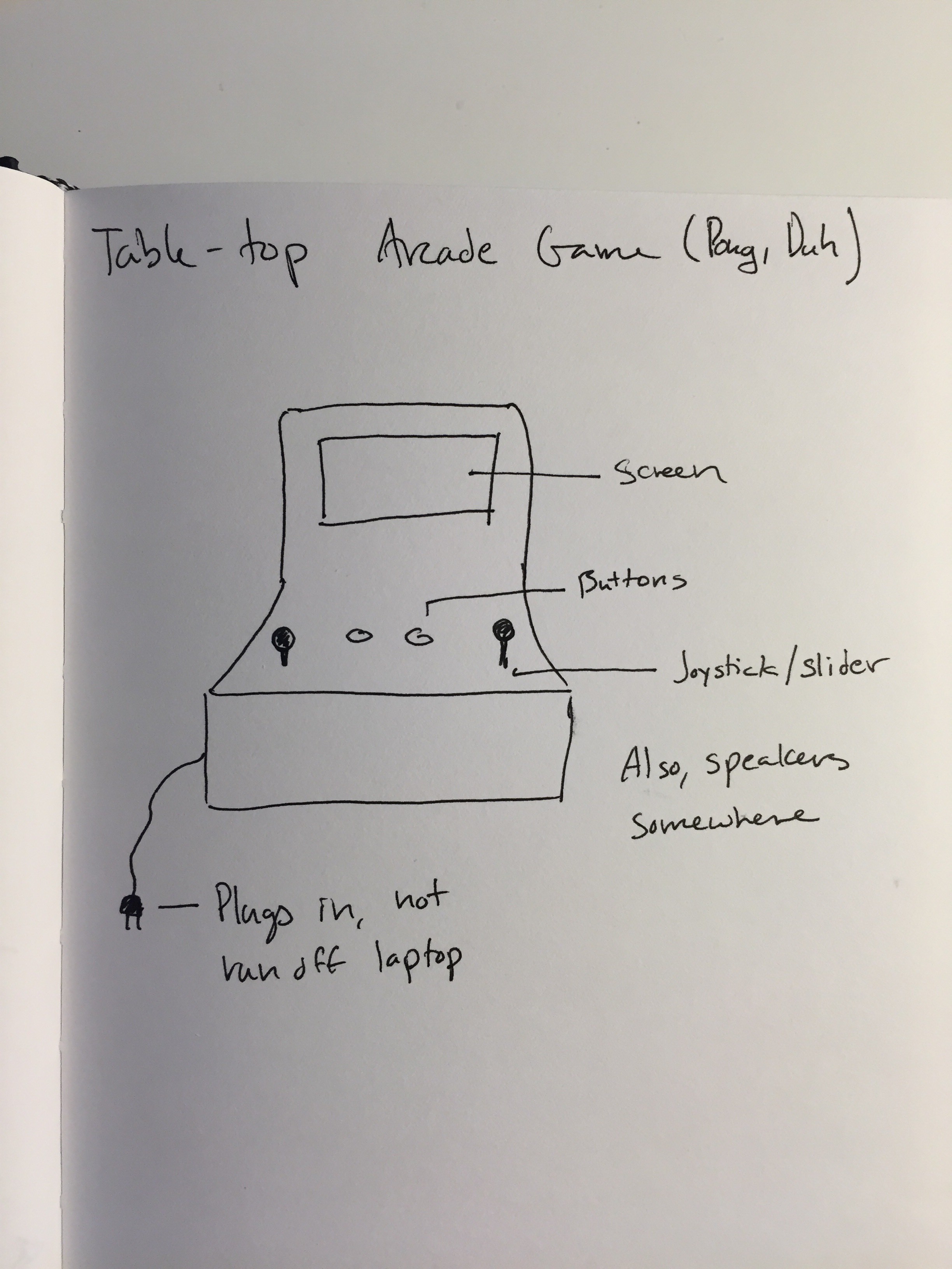
After a whole bunch of brainstorming I’ve realized that the project that I’d really like to build is a small cabinet for the pong game I’ve been eking out. I kept trying to come up with ideas for something that’s more artistic and cool, but I kept coming back to this project. So, I guess the best thing to do is just embrace it.
So far the semester has felt like a whole bunch of bits and pieces. I think what really interests me about building this is bringing everything together and solidifying what I have learned in PComp and ICM so far.
I wanted to make some controllers for the pong game I’ve been plugging away at for ICM. Constructing the prototypes was pretty straight forward, but getting the code to work has been a whole other thing.
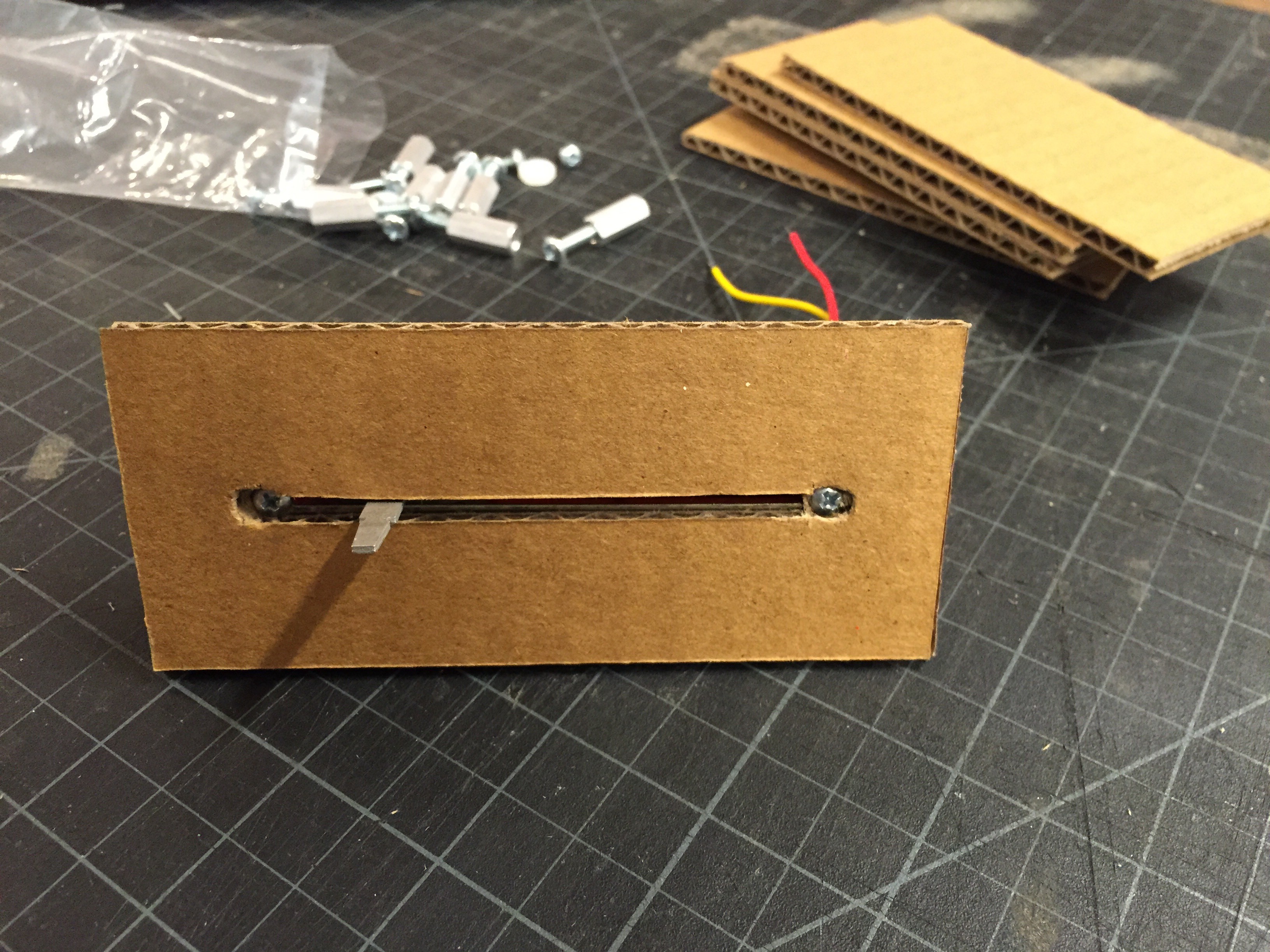
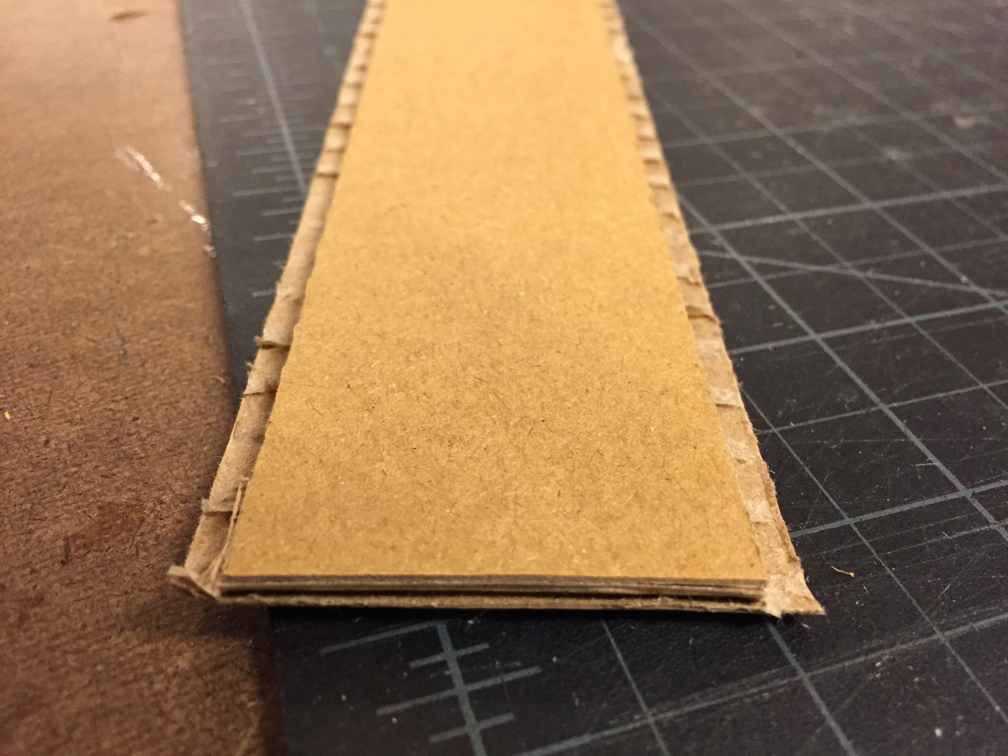
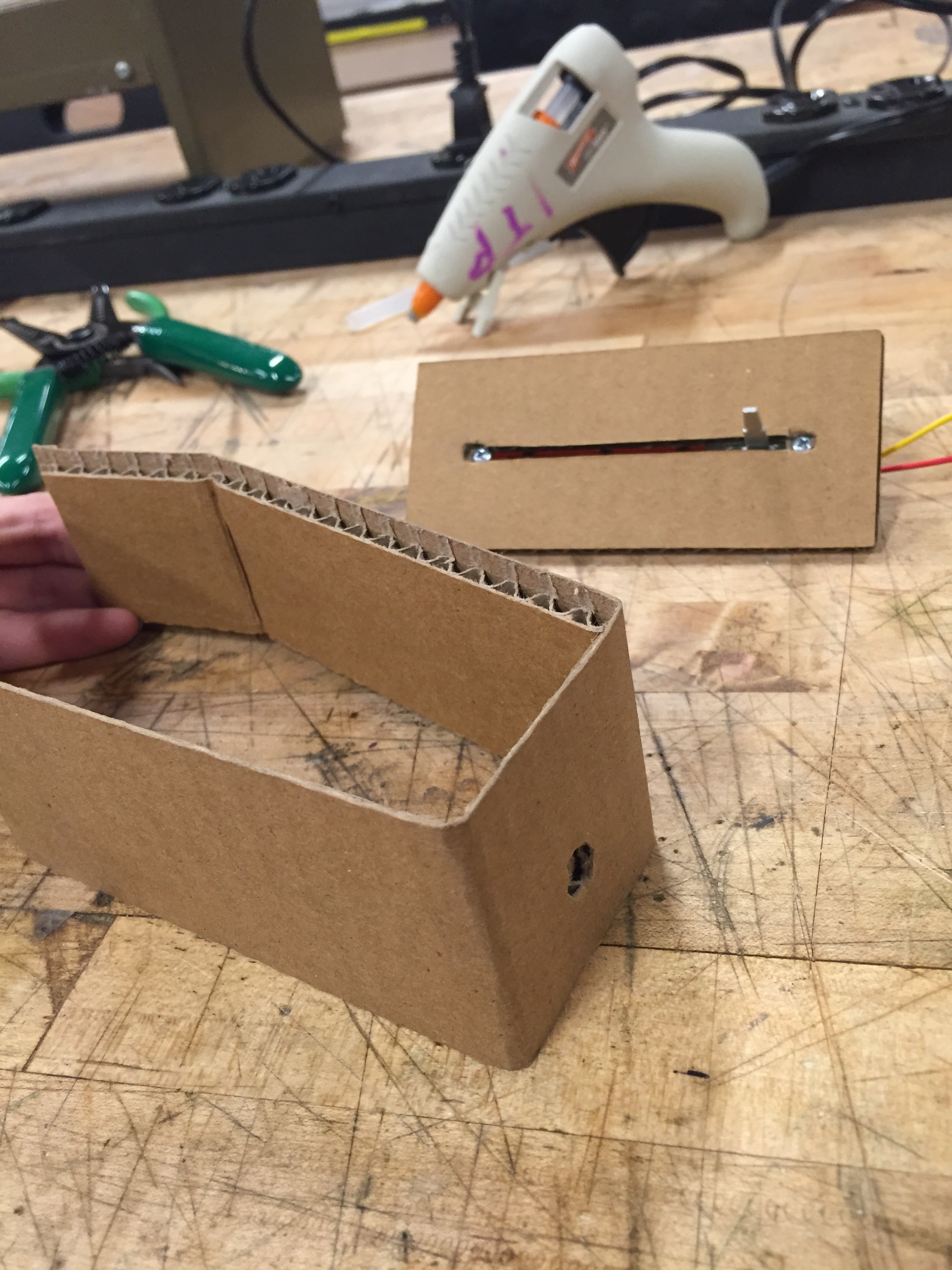
I had some slide pots already from a previous project, so all I really needed to do was make a housing for them. Cardboard is free, and I actually quite like it as a material.
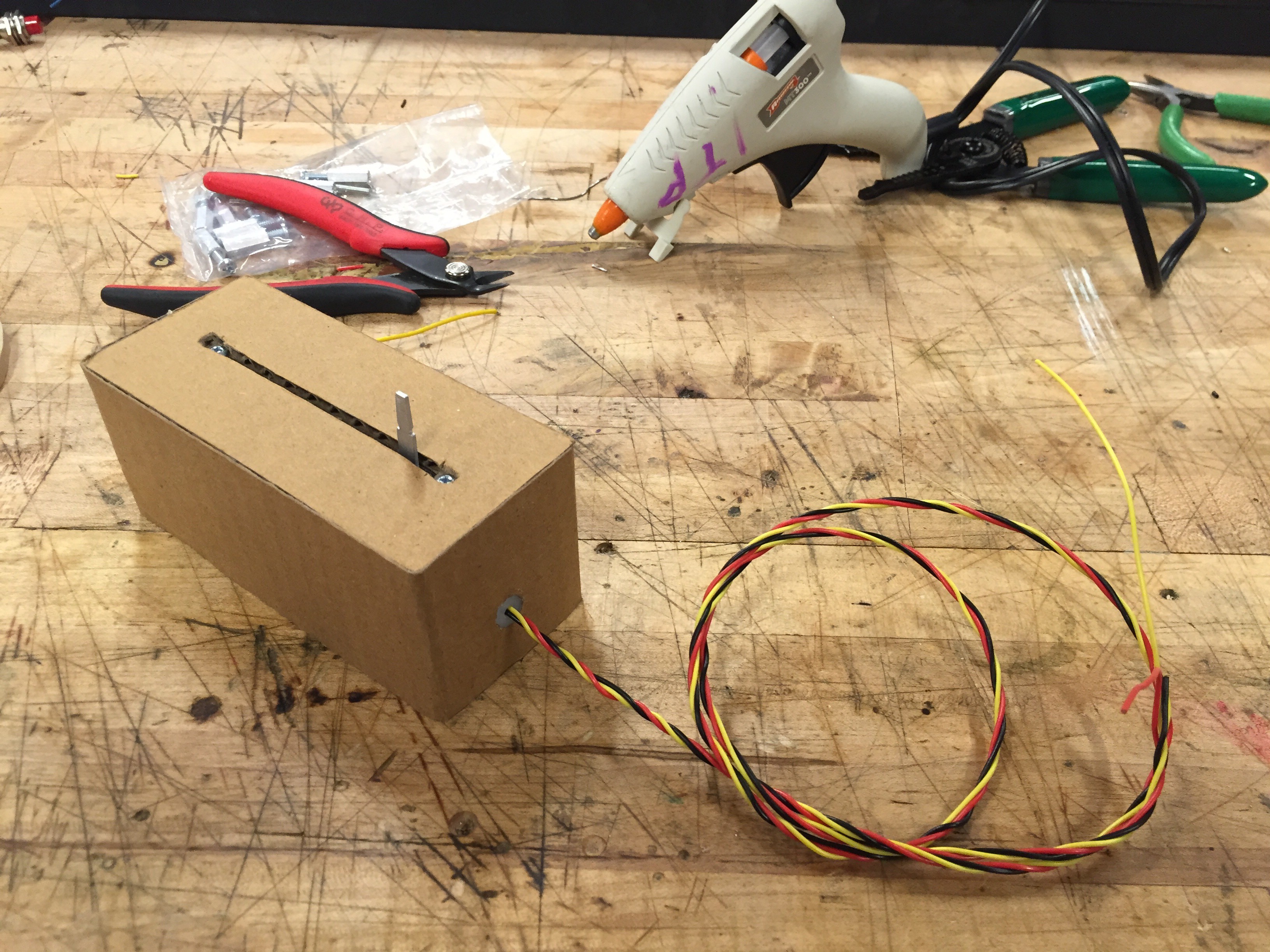
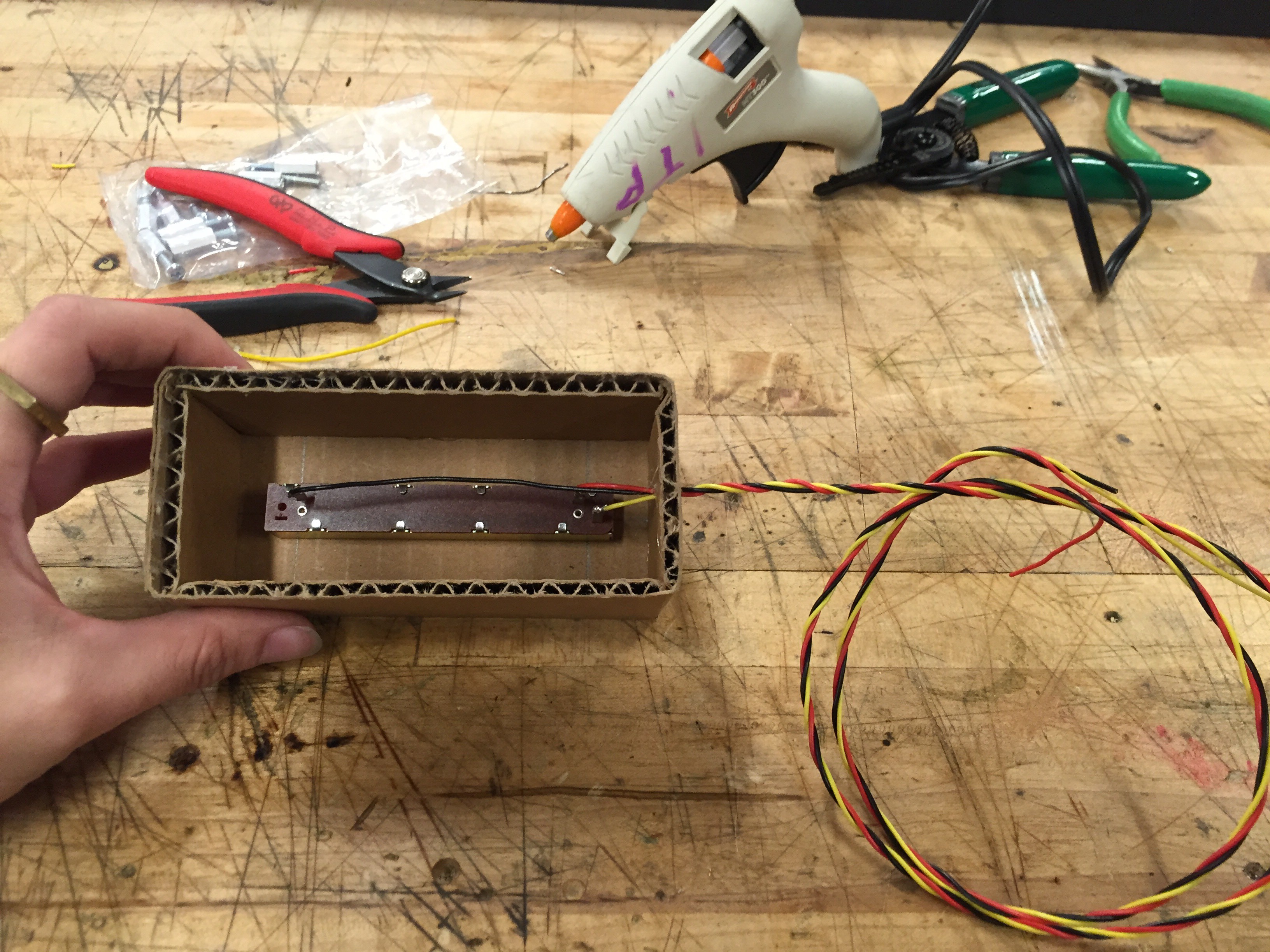
Slide pots and cut cardboard.Pot screwed into the top of the housing.This way there will be no visible corrugated edges.The sides of the housing are all out of one long piece of cardboardThe top is hot glued to the sides. The wires are threaded through a plastic nut. This gives a nice finish and stops the soldering from getting broken if the wires are pulled on.The view from the bottom.The wiring.
The Arduino code seems to work just fine:
void setup() {
  Serial.begin(9600);

}

void loop() {
//send two things separated by a commma

 int slideOne = analogRead(A0);                  // read the input pin
 int mappedSlideOne = map(slideOne, 0, 1023, 0, 255); // remap the pot value to fit in 1 byte
 int slideTwo = analogRead(A5);                  // read the input pin
 int mappedSlideTwo = map(slideTwo, 0, 1023, 0, 255); // remap the pot value to fit in 1 byte
 Serial.print(mappedSlideOne);                             // print it out the serial port
 Serial.print(",");
 Serial.println(mappedSlideTwo);
 delay(1);
}
But the p5.js code keeps coming up ‘undefined’. I can’t figure out what’s wrong with the code. After I’ve gotten that worked out it should be pretty easy to drop it into the pong code I’ve already been working on.
var serial; // variable to hold an instance of the serialport library
var portName = '/dev/cu.usbmodem1421'; // fill in your serial port name here
var inData; // for incoming serial data
var myData;
var input;
var input2;
var inString;


function setup() {
  serial = new p5.SerialPort(); // make a new instance of the serialport library
  serial.on('list', printList); // set a callback function for the serialport list event
  serial.on('connected', serverConnected); // callback for connecting to the server
  serial.on('open', portOpen); // callback for the port opening
  serial.on('data', serialEvent); // callback for when new data arrives
  serial.on('error', serialError); // callback for errors
  serial.on('close', portClose); // callback for the port closing
  serial.open(portName); // open a serial port

  serial.list(); // list the serial ports
  createCanvas(400, 300);
}


function draw() {
  background(0);
  fill(255);
  //text("sensor value: " + input + "," + input2, 30, 30);
  text("sensor value: " + input, 30, 30);
  text("hello world", 30, 50);
  print(inString);
}


function serverConnected() {
  println('connected to server.');
}

function portOpen() {
  println('the serial port opened.');
}

function serialEvent() {
  inString = serial.readStringUntil('\r\n');

  if (inString.length > 0) {
    var parts = inString.split(","); //split the incoming into an array based on the comma
    input = int(parts[0]);
    input2 = int(parts[1]);
    print(input2 + "Got data" + input);
  }

}

function serialError(err) {
  println('Something went wrong with the serial port. ' + err);
}

function portClose() {
  println('The serial port closed.');
}


// get the list of ports:
function printList(portList) {
  // portList is an array of serial port names
  for (var i = 0; i < portList.length; i++) {
    // Display the list the console:
    println(i + " " + portList[i]);
  }
}
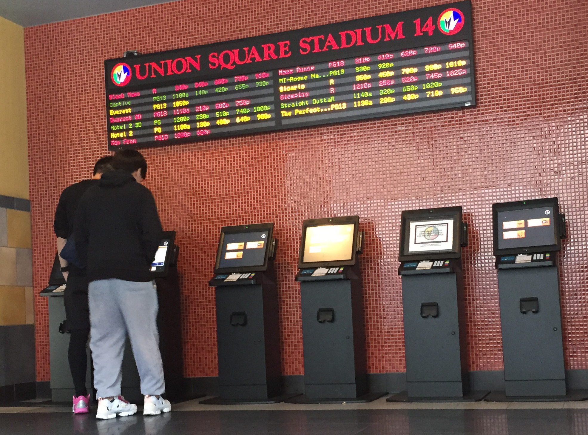
These automatic kiosks are everywhere now. These machines are only minimally interactive, but I think they are especially interesting. I do not like using them, but I like it more than actually going up to the ticket window and talking to an actual person to buy my ticket. That dynamic seems off-putting and strange. This particular batch is from the Regal Cinema in Union Square. People can use them to buy tickets for movies, or pick up tickets that they have already bought online.
Most people coming into the theater seem to gravitate towards the automatic kiosks. I didn’t actually take notes on the numbers, but it seemed true. There are enough kiosks that no one has to wait to buy a ticket, even when there is a large crowd and several kiosks are out of order.
I timed 20 transactions from first screen tap to picking up printed tickets.
0:59.19
0:46.23
1:06.35
0:50.79
0:47.32
01:36.76
0:15.54
1:25.37
0:56.24
0:50.55
2:04.54
1:36.12
2:22.20
3:29.77
0:38.26
1:00.36
0:58.21
1:02.47
0:04.95
1:03.81
Avg 1:11.75
I was surprised that the average time was around a minute, it seemed so much longer than that. Most of the time seemed to be spent tapping through informational interfaces, and the most common problem seemed to be with the credit card readers.
The whole time I was there I expected at least one user to get really angrily frustrated with the process, but no one did. Even the people who had trouble seemed to take it all in stride. They tried different credit cards without prompting from the machine and solved their own problems. It seems like at this point everyone has a pretty good mental model for how these things work. Also, I wonder if everyone has very low expectations for how the machines will work so event the fact that it works at all is a success.
Even after observing folks buying tickets I’m left wondering why everyone prefers this over talking with a person. Quicker process? Aversion to talking with others? I guess that one needs more research.