TLC5940NT from coldsoup753 on Vimeo.
I planned on using the TLC5940NT to drive the LEDs for this project. After finding the TLC5940NT library setting up the LEDs was pretty straightforward. I wrote sketch that would change the LEDs to a color of my choice and it seemed like it was just a matter of dropping that code into the accelerometer sketch.
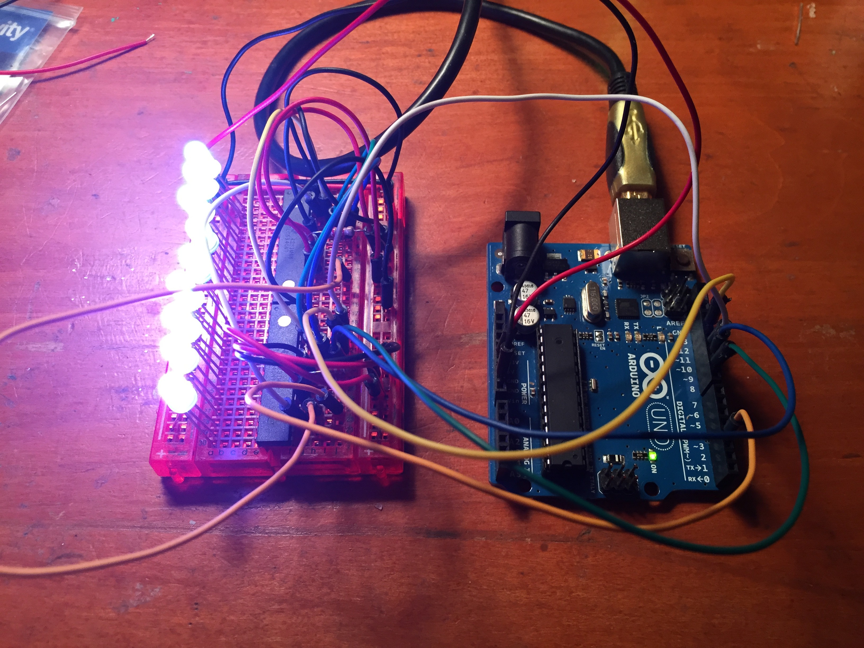
However, when I combined the TLC5940NT and the ADXL345, things just didn’t work. The LEDs changed to all different colors and they did not respond to the accelerometer. My best guess was that something from the accelerometer was throwing the clock off and that change was affecting the PWM in the TLC5940NTs. Also, I noticed the colors were changing every time the ADXL345 sent an interrupt. There were some good clues to investigate, but it wasn’t something that I really understood or could get fixed before the project presentation. In the end I decided to leave out the TLC5940NT, in favor of a bare bones proof of concept that worked.
Code to change the color of the LEDs, adapted from the TLC5940NT library example code.
/*
    Basic Pin setup:
    ------------                                  ---u----
    ARDUINO   13|-> SCLK (pin 25)           OUT1 |1     28| OUT channel 0
              12|                           OUT2 |2     27|-> GND (VPRG)
              11|-> SIN (pin 26)            OUT3 |3     26|-> SIN (pin 11)
              10|-> BLANK (pin 23)          OUT4 |4     25|-> SCLK (pin 13)
               9|-> XLAT (pin 24)             .  |5     24|-> XLAT (pin 9)
               8|                             .  |6     23|-> BLANK (pin 10)
               7|                             .  |7     22|-> GND
               6|                             .  |8     21|-> VCC (+5V)
               5|                             .  |9     20|-> 2K Resistor -> GND
               4|                             .  |10    19|-> +5V (DCPRG)
               3|-> GSCLK (pin 18)            .  |11    18|-> GSCLK (pin 3)
               2|                             .  |12    17|-> SOUT
               1|                             .  |13    16|-> XERR
               0|                           OUT14|14    15| OUT channel 15
    ------------                                  --------

    -  Put the longer leg (anode) of the LEDs in the +5V and the shorter leg
         (cathode) in OUT(0-15).
    -  +5V from Arduino -> TLC pin 21 and 19     (VCC and DCPRG)
    -  GND from Arduino -> TLC pin 22 and 27     (GND and VPRG)
    -  digital 3        -> TLC pin 18            (GSCLK)
    -  digital 9        -> TLC pin 24            (XLAT)
    -  digital 10       -> TLC pin 23            (BLANK)
    -  digital 11       -> TLC pin 26            (SIN)
    -  digital 13       -> TLC pin 25            (SCLK)
    -  The 2K resistor between TLC pin 20 and GND will let ~20mA through each
       LED.  To be precise, it's I = 39.06 / R (in ohms).  This doesn't depend
       on the LED driving voltage.
    - (Optional): put a pull-up resistor (~10k) between +5V and BLANK so that
                  all the LEDs will turn off when the Arduino is reset.

    If you are daisy-chaining more than one TLC, connect the SOUT of the first
    TLC to the SIN of the next.  All the other pins should just be connected
    together:
        BLANK on Arduino -> BLANK of TLC1 -> BLANK of TLC2 -> ...
        XLAT on Arduino  -> XLAT of TLC1  -> XLAT of TLC2  -> ...
    The one exception is that each TLC needs it's own resistor between pin 20
    and GND.

    This library uses the PWM output ability of digital pins 3, 9, 10, and 11.
    Do not use analogWrite(...) on these pins.

    This sketch does the Knight Rider strobe across a line of LEDs.

    Alex Leone , 2009-02-03 */

#include "Tlc5940.h"

void setup()
{
  /* Call Tlc.init() to setup the tlc.
     You can optionally pass an initial PWM value (0 - 4095) for all channels.*/
  Tlc.init(0);
}

/* This loop will create a Knight Rider-like effect if you have LEDs plugged
   into all the TLC outputs.  NUM_TLCS is defined in "tlc_config.h" in the
   library folder.  After editing tlc_config.h for your setup, delete the
   Tlc5940.o file to save the changes. */

void loop()
{

 showRGB(10000);

  }


void showRGB(int color)
{
  int redIntensity;
  int greenIntensity;
  int blueIntensity;

// This function translates a number between 0 and 767 into a
// specific color on the RGB LED. If you have this number count
// through the whole range (0 to 767), the LED will smoothly
// change color through the entire spectrum.

  // Here we'll use an "if / else" statement to determine which
  // of the three (R,G,B) zones x falls into. Each of these zones
  // spans 4095 because the Tlc5940 wants a number from 0 to 4095.

  // In each of these zones, we'll calculate the brightness
  // for each of the red, green, and blue LEDs within the RGB LED.
  // x = 4096
  // color = a number from 0 to 12287


  if (color <= 4095)          // zone 1
  {
    redIntensity = 4095 - color;    // red goes from on to off
    greenIntensity = color;        // green goes from off to on
    blueIntensity = 0;             // blue is always off
  }
  else if (color <= 8191) // zone 2 { redIntensity = 0; // red is always off greenIntensity = 8191 - (color - 4096); // green on to off blueIntensity = (color - 4096); // blue off to on } else // color >= 8192       // zone 3
  {
    redIntensity = (color - 8192);         // red off to on
    greenIntensity = 0;                   // green is always off
    blueIntensity = 8191 - (color - 8192);  // blue on to off
  }

  // Now that the brightness values have been set, command the LED
  // to those values
  // 1
  Tlc.set(0, redIntensity);
  Tlc.set(1, blueIntensity);
  Tlc.set(2, greenIntensity);
  //2
  Tlc.set(3, redIntensity);
  Tlc.set(4, blueIntensity);
  Tlc.set(5, greenIntensity);
  //3
  Tlc.set(6, redIntensity);
  Tlc.set(7, blueIntensity);
  Tlc.set(8, greenIntensity);
  //4
  Tlc.set(9, redIntensity);
  Tlc.set(10, blueIntensity);
  Tlc.set(11, greenIntensity);
  //5
  Tlc.set(12, redIntensity);
  Tlc.set(13, blueIntensity);
  Tlc.set(14, greenIntensity);
  //6
  Tlc.set(15, redIntensity);
  Tlc.set(16, blueIntensity);
  Tlc.set(17, greenIntensity);
  //7
  Tlc.set(18, redIntensity);
  Tlc.set(19, blueIntensity);
  Tlc.set(20, greenIntensity);
  //8
  Tlc.set(21, redIntensity);
  Tlc.set(22, blueIntensity);
  Tlc.set(23, greenIntensity);
  //9
  Tlc.set(24, redIntensity);
  Tlc.set(25, blueIntensity);
  Tlc.set(26, greenIntensity);
  //10
  Tlc.set(27, redIntensity);
  Tlc.set(28, blueIntensity);
  Tlc.set(29, greenIntensity);
  Tlc.update();
}