This project uses the resistance in a graphite pencil to change the colors of an RGB LED. I built the two parts separately to make sure they worked before combining them.
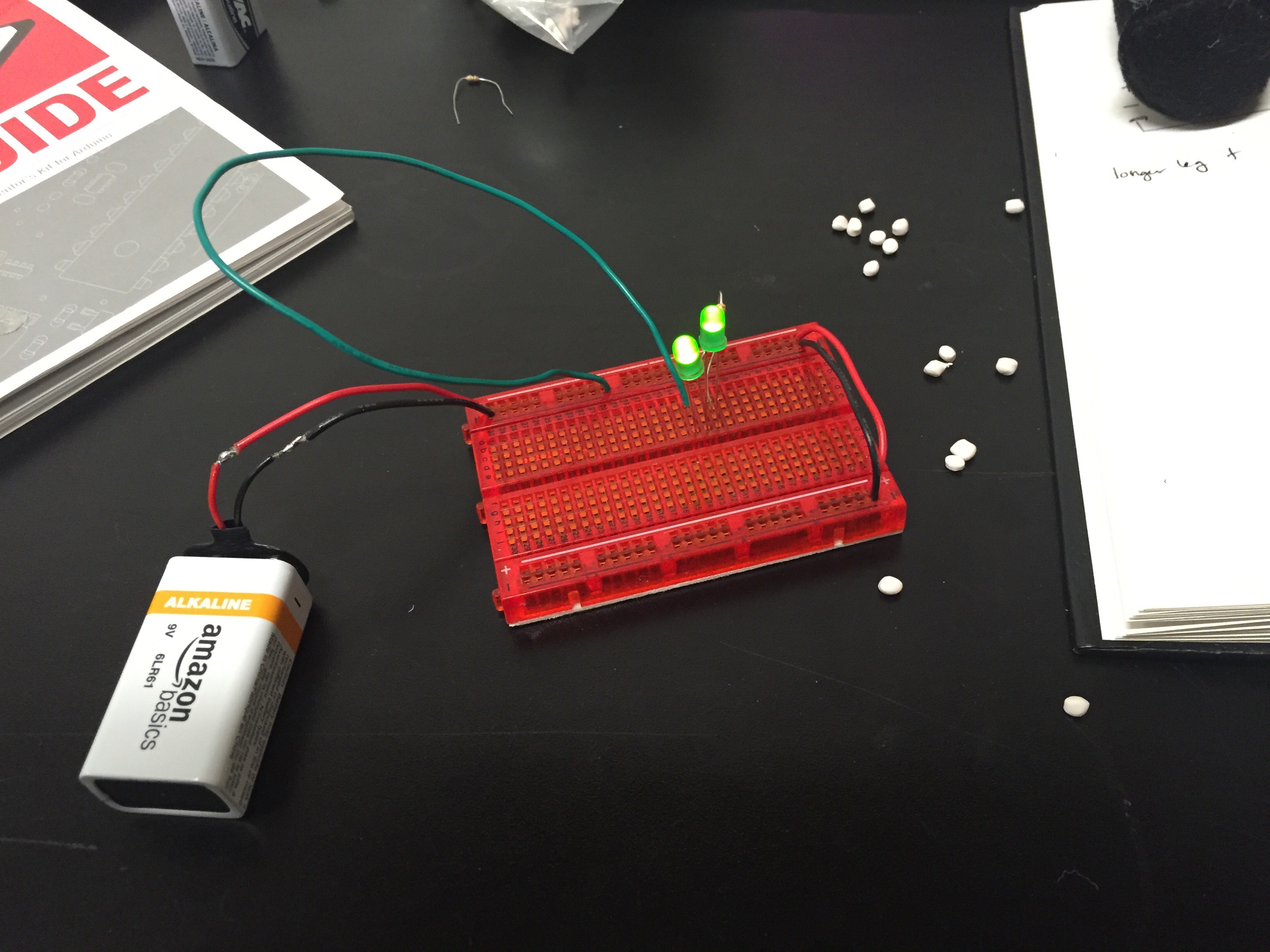
I used the directions and some example code, included at the bottom of the page, to make the RGB LED work. Getting this up and running was pretty easy.
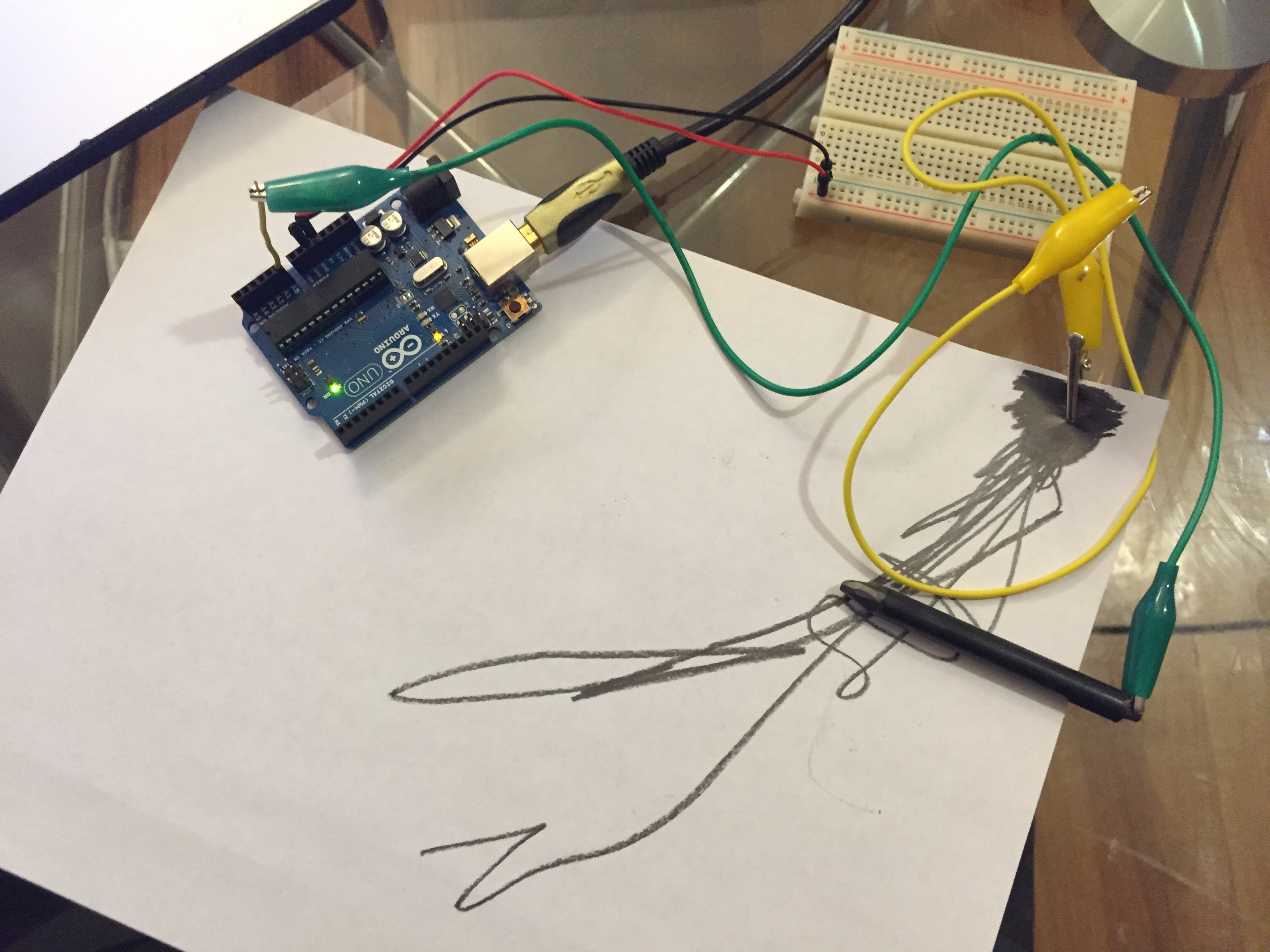
Hooking up the pencil was fun, I created a simple circuit and tested it by writing to serial.
Then I put the two together to get this:
int pencilResistance;


int RED_PIN = 9; //set pins for LEDs
int GREEN_PIN = 10;
int BLUE_PIN = 11;


void setup() {
  Serial.begin(9600); //typical speed for communication
  pinMode(0, INPUT);
  pinMode(RED_PIN, OUTPUT);
  pinMode(GREEN_PIN, OUTPUT);
  pinMode(BLUE_PIN, OUTPUT);

}


void loop() {
  pencilResistance = analogRead(0);
  //Serial.println(pencilResistance);

  int pencilRGB = map(pencilResistance, 0, 1023, 0, 767);
  Serial.println(pencilRGB);

  showRGB(pencilRGB);


}


void showRGB(int color)
{
  int redIntensity;
  int greenIntensity;
  int blueIntensity;

  if (color <= 255)          // zone 1
  {
    redIntensity = 255 - color;    // red goes from on to off
    greenIntensity = color;        // green goes from off to on
    blueIntensity = 0;             // blue is always off
  }
  else if (color <= 511) // zone 2 { redIntensity = 0; // red is always off greenIntensity = 255 - (color - 256); // green on to off blueIntensity = (color - 256); // blue off to on } else // color >= 512       // zone 3
  {
    redIntensity = (color - 512);         // red off to on
    greenIntensity = 0;                   // green is always off
    blueIntensity = 255 - (color - 512);  // blue on to off
  }

  // Now that the brightness values have been set, command the LED
  // to those values

  analogWrite(RED_PIN, redIntensity);
  analogWrite(BLUE_PIN, blueIntensity);
  analogWrite(GREEN_PIN, greenIntensity);
}
That’s it!
There’s quite a bit more to the example code Sparkfun provided, but I didn’t need all of it:
const int RED_PIN = 9; //set pins for LEDs
const int GREEN_PIN = 10;
const int BLUE_PIN = 11;

int DISPLAY_TIME = 100;  // In milliseconds for the set colors

void setup()
{
  // Here we'll configure the Arduino pins we're using to
  // drive the LED to be outputs:
  Serial.begin(9600); //typical speed for communication
  pinMode(0, INPUT);
  pinMode(RED_PIN, OUTPUT);
  pinMode(GREEN_PIN, OUTPUT);
  pinMode(BLUE_PIN, OUTPUT);
}


void loop()
{

  mainColors();


  showSpectrum();
}


// Here's the mainColors() function we've written.

// This function displays the eight "main" colors that the RGB LED
// can produce. If you'd like to use one of these colors in your
// own sketch, you cancopy and paste that section into your code.

void mainColors()
{
  // Off (all LEDs off):

  digitalWrite(RED_PIN, LOW);
  digitalWrite(GREEN_PIN, LOW);
  digitalWrite(BLUE_PIN, LOW);

  delay(1000);

  // Red (turn just the red LED on):

  digitalWrite(RED_PIN, HIGH);
  digitalWrite(GREEN_PIN, LOW);
  digitalWrite(BLUE_PIN, LOW);

  delay(1000);

  // Green (turn just the green LED on):

  digitalWrite(RED_PIN, LOW);
  digitalWrite(GREEN_PIN, HIGH);
  digitalWrite(BLUE_PIN, LOW);

  delay(1000);

  // Blue (turn just the blue LED on):

  digitalWrite(RED_PIN, LOW);
  digitalWrite(GREEN_PIN, LOW);
  digitalWrite(BLUE_PIN, HIGH);

  delay(1000);

  // Yellow (turn red and green on):

  digitalWrite(RED_PIN, HIGH);
  digitalWrite(GREEN_PIN, HIGH);
  digitalWrite(BLUE_PIN, LOW);

  delay(1000);

  // Cyan (turn green and blue on):

  digitalWrite(RED_PIN, LOW);
  digitalWrite(GREEN_PIN, HIGH);
  digitalWrite(BLUE_PIN, HIGH);

  delay(1000);

  // Purple (turn red and blue on):

  digitalWrite(RED_PIN, HIGH);
  digitalWrite(GREEN_PIN, LOW);
  digitalWrite(BLUE_PIN, HIGH);

  delay(1000);

  // White (turn all the LEDs on):

  digitalWrite(RED_PIN, HIGH);
  digitalWrite(GREEN_PIN, HIGH);
  digitalWrite(BLUE_PIN, HIGH);

  delay(1000);
}


// Below are two more functions we've written,
// showSpectrum() and showRGB().

// showRGB() displays a single color on the RGB LED.
// You call showRGB() with the number of a color you want
// to display.

// showSpectrum() steps through all the colors of the RGB LED,
// displaying a rainbow. showSpectrum() actually calls showRGB()
// over and over to do this.

// We'll often break tasks down into individual functions like
// this, which makes your sketches easier to follow, and once
// you have a handy function, you can reuse it in your other
// programs.


// showSpectrum()

// This function steps through all the colors of the RGB LED.
// It does this by stepping a variable from 0 to 768 (the total
// number of colors), and repeatedly calling showRGB() to display
// the individual colors.

// In this function, we're using a "for() loop" to step a variable
// from one value to another, and perform a set of instructions
// for each step. For() loops are a very handy way to get numbers
// to count up or down.

// Every for() loop has three statements separated by semicolons:

//   1. Something to do before starting

//   2. A test to perform; as long as it's true,
//      it will keep looping

//   3. Something to do after each loop (usually
//      increase a variable)

// For the for() loop below, these are the three statements:

//   1. x = 0;     Before starting, make x = 0.

//   2. x < 768;   While x is less than 768, run the
//                 following code.

//   3. x++        Putting "++" after a variable means
//                 "add one to it". (You can also use "x = x + 1")

// Every time you go through the loop, the statements following
// the loop (those within the brackets) will run.

// And when the test in statement 2 is finally false, the sketch
// will continue.


void showSpectrum()
{
  int x;  // define an integer variable called "x"

  // Now we'll use a for() loop to make x count from 0 to 767
  // (Note that there's no semicolon after this line!
  // That's because the for() loop will repeat the next
  // "statement", which in this case is everything within
  // the following brackets {} )

  for (x = 0; x < 768; x++)

  // Each time we loop (with a new value of x), do the following:

  {
    showRGB(x);  // Call RGBspectrum() with our new x
    delay(10);   // Delay for 10 ms (1/100th of a second)
  }
}


// showRGB()

// This function translates a number between 0 and 767 into a
// specific color on the RGB LED. If you have this number count
// through the whole range (0 to 767), the LED will smoothly
// change color through the entire spectrum.

// The "base" numbers are:
// 0   = pure red
// 255 = pure green
// 511 = pure blue
// 767 = pure red (again)

// Numbers between the above colors will create blends. For
// example, 640 is midway between 512 (pure blue) and 767
// (pure red). It will give you a 50/50 mix of blue and red,
// resulting in purple.

// If you count up from 0 to 767 and pass that number to this
// function, the LED will smoothly fade between all the colors.
// (Because it starts and ends on pure red, you can start over
// at 0 without any break in the spectrum).


void showRGB(int color)
{
  int redIntensity;
  int greenIntensity;
  int blueIntensity;

  // Here we'll use an "if / else" statement to determine which
  // of the three (R,G,B) zones x falls into. Each of these zones
  // spans 255 because analogWrite() wants a number from 0 to 255.

  // In each of these zones, we'll calculate the brightness
  // for each of the red, green, and blue LEDs within the RGB LED.

  if (color <= 255)          // zone 1
  {
    redIntensity = 255 - color;    // red goes from on to off
    greenIntensity = color;        // green goes from off to on
    blueIntensity = 0;             // blue is always off
  }
  else if (color <= 511) // zone 2 { redIntensity = 0; // red is always off greenIntensity = 255 - (color - 256); // green on to off blueIntensity = (color - 256); // blue off to on } else // color >= 512       // zone 3
  {
    redIntensity = (color - 512);         // red off to on
    greenIntensity = 0;                   // green is always off
    blueIntensity = 255 - (color - 512);  // blue on to off
  }

  // Now that the brightness values have been set, command the LED
  // to those values

  analogWrite(RED_PIN, redIntensity);
  analogWrite(BLUE_PIN, blueIntensity);
  analogWrite(GREEN_PIN, greenIntensity);
}